There's a profound difference between emulation and the real thing. While my previous post covered running CP/M on a software-based Z80 emulator, this post documents the journey of bringing CP/M 2.2 to life on actual Z80 silicon - a real Zilog Z80 CPU executing real machine code, with 1MB of DRAM and SD card storage for disk images.
The result? A fully functional CP/M system running Zork, all on an Arduino Mega 2560 acting as the glue between vintage and modern technology.
The Hardware Stack
Building a working CP/M system requires three essential components: a CPU, memory, and storage. Here's what I used:
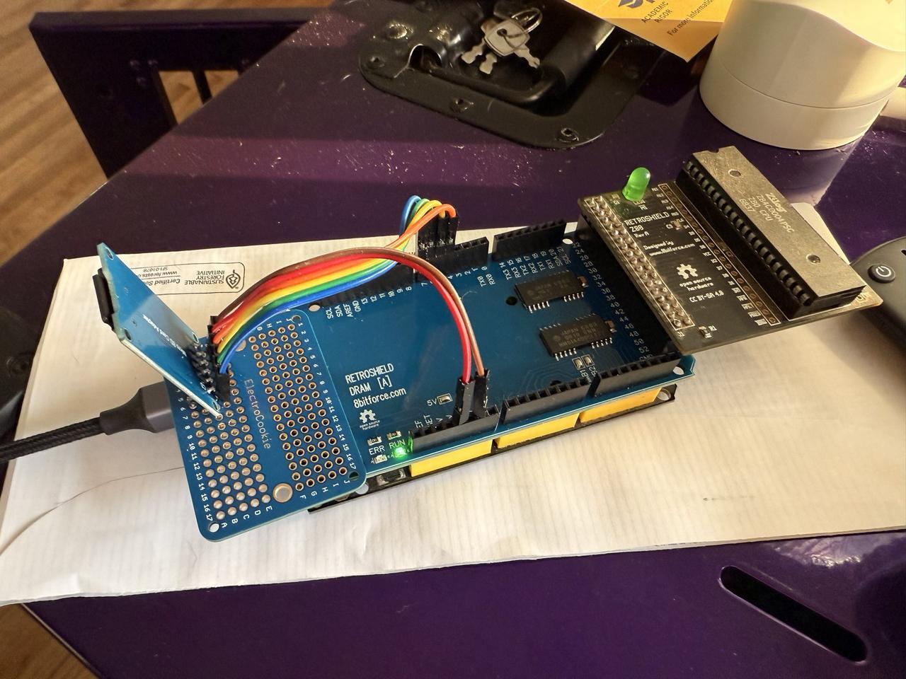
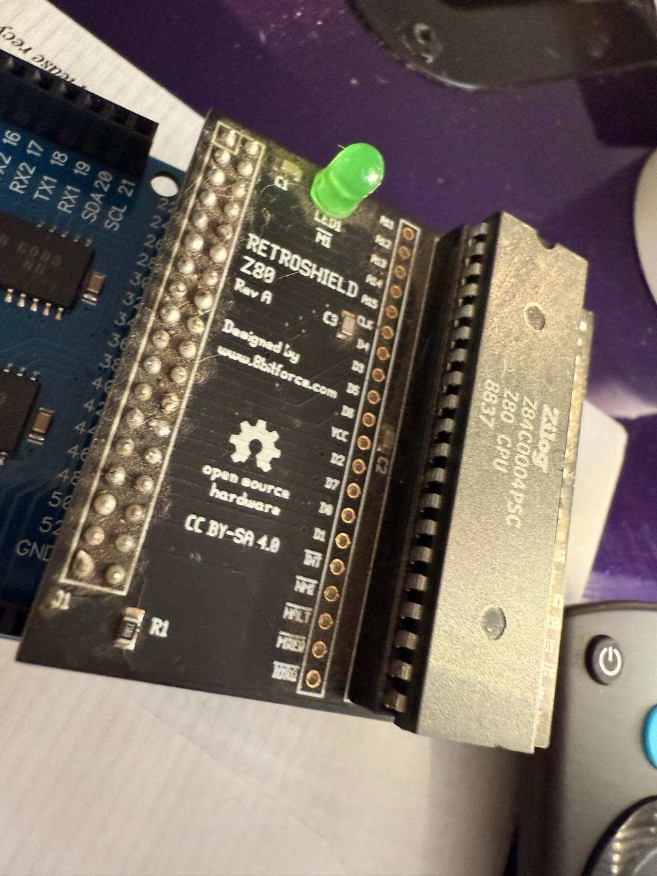
The RetroShield Z80
The RetroShield from 8bitforce is a clever piece of engineering. It's a shield that holds a real Z80 CPU and lets an Arduino Mega control it cycle-by-cycle. The Arduino provides the clock, handles bus transactions, and emulates peripherals - but the Z80 is doing the actual computation.
The RetroShield uses nearly every pin on the Arduino Mega:
| Function | Arduino Pins |
|---|---|
| Address Bus (A0-A15) | Pins 22-37 |
| Data Bus (D0-D7) | Pins 42-49 |
| Control Signals | Pins 38-41, 50-53 |
This pin-hungry design means we need to be creative about adding peripherals.
KDRAM2560: 1MB of Dynamic RAM
The KDRAM2560 is another 8bitforce product - a DRAM shield that provides a full megabyte of memory to the Arduino Mega. It uses the analog pins (A0-A15) for its interface, leaving digital pins available for other uses.
Why DRAM instead of SRAM? Cost and density. A megabyte of SRAM would be expensive and physically large. DRAM is cheap but requires periodic refresh to maintain data integrity. The KDRAM2560 library handles this automatically using one of the Arduino's hardware timers.
For CP/M, we only need 64KB of the available 1MB, but having extra memory opens possibilities for RAM disks or bank switching in future projects.
#define DRAM_REFRESH_USE_TIMER_1
#include <kdram2560.h>

void setup() {
    // Initialize DRAM - this also starts the refresh interrupt
    if (DRAM.begin(&Serial)) {
        Serial.println("KDRAM2560: OK (1MB DRAM)");
    } else {
        Serial.println("KDRAM2560: FAILED!");
        while (1) {}  // Halt
    }
}
The API is beautifully simple:
// Read a byte from any address in the 1MB space
byte data = DRAM.read8(address);

// Write a byte
DRAM.write8(address, data);
Internally, the library handles the complex multiplexed addressing that DRAM requires - splitting the 20-bit address into row and column components, managing RAS/CAS timing, and ensuring refresh cycles happen frequently enough to prevent data loss.
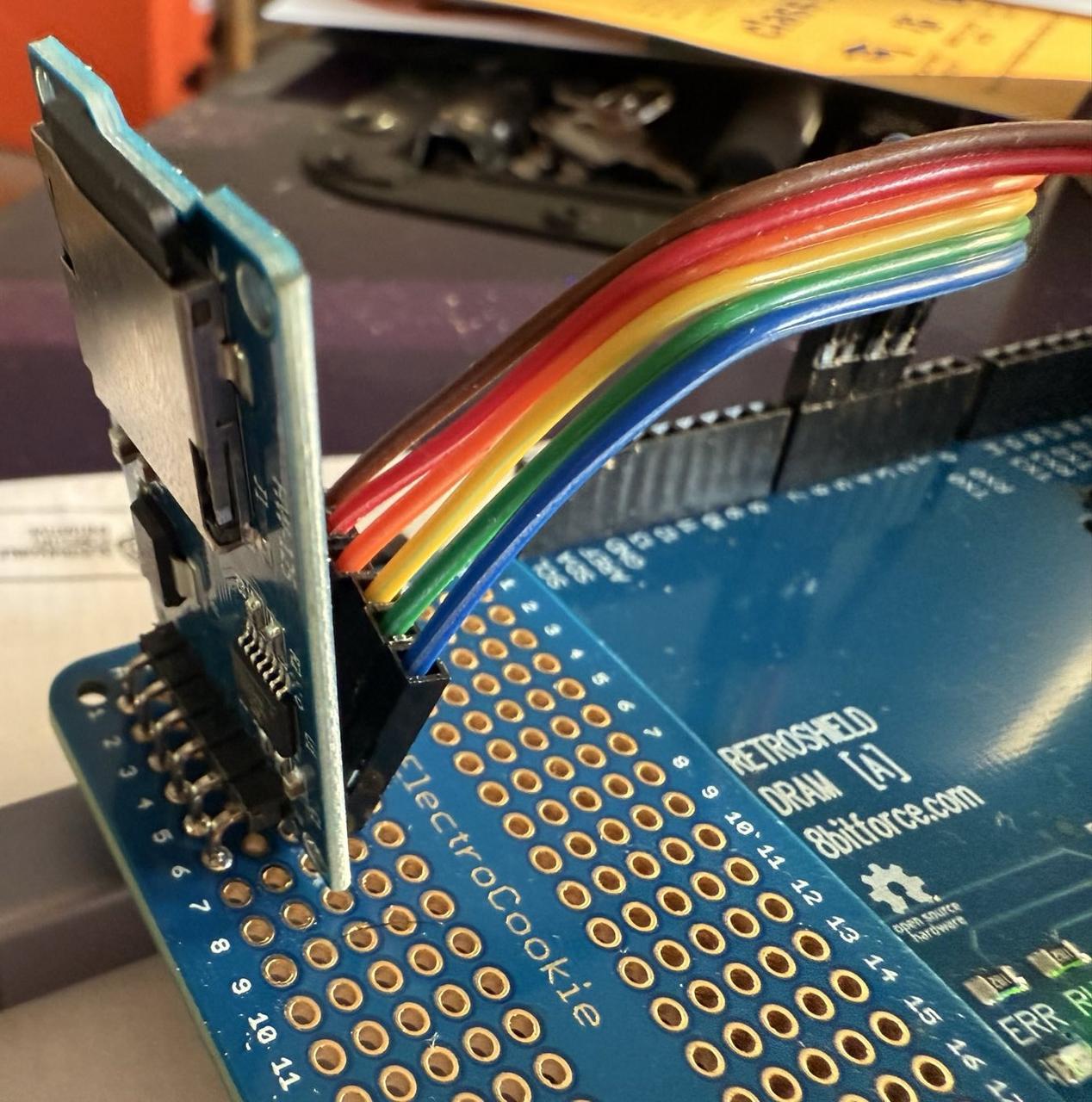
Software SPI SD Card
Here's where things get interesting. The obvious choice for SD card storage would be the Arduino's hardware SPI on pins 50-53. But look back at that pin table - the RetroShield uses pins 50-53 for Z80 control signals!
The solution is software SPI - bit-banging the SPI protocol on different pins. I chose pins 4-7, safely away from both the RetroShield and KDRAM2560:
| SD Card Pin | Arduino Pin |
|---|---|
| MISO | Pin 4 |
| MOSI | Pin 5 |
| SCK | Pin 6 |
| CS | Pin 7 |
The SdFat library supports software SPI through its SoftSpiDriver template class. One important note: you must set SPI_DRIVER_SELECT to 2 in SdFatConfig.h to enable this:
// In SdFat/src/SdFatConfig.h
#define SPI_DRIVER_SELECT 2  // Enable software SPI
Then in your sketch:
#include "SdFat.h"

const uint8_t SOFT_MISO_PIN = 4;
const uint8_t SOFT_MOSI_PIN = 5;
const uint8_t SOFT_SCK_PIN  = 6;
const uint8_t SD_CS_PIN     = 7;

SoftSpiDriver<SOFT_MISO_PIN, SOFT_MOSI_PIN, SOFT_SCK_PIN> softSpi;
#define SD_CONFIG SdSpiConfig(SD_CS_PIN, DEDICATED_SPI, SD_SCK_MHZ(0), &softSpi)

SdFs sd;

void setup() {
    if (sd.begin(SD_CONFIG)) {
        Serial.println("SD Card: OK (Software SPI)");
    }
}
Software SPI is slower than hardware SPI - roughly 20-50 KB/s compared to 1-2 MB/s. For loading programs at boot and occasional disk access, this is perfectly acceptable. You won't notice the difference playing Zork.
The Complete System Architecture
Here's how all the pieces fit together:
┌─────────────────────────────────────────────────────────────┐
│                      Arduino Mega 2560                      │
├─────────────────────────────────────────────────────────────┤
│  Z80 RetroShield (top layer)                                │
│    Real Zilog Z80 CPU @ ~100kHz                             │
│    Address: pins 22-37 (directly mapped)                    │
│    Data: pins 42-49 (directly mapped)                       │
│    Control: pins 38-41, 50-53                               │
├─────────────────────────────────────────────────────────────┤
│  KDRAM2560 (middle layer)                                   │
│    1MB DRAM via analog pins A0-A15                          │
│    Timer 1 interrupt for automatic refresh                  │
│    Only 64KB used for Z80 address space                     │
├─────────────────────────────────────────────────────────────┤
│  MicroSD Card (external, via jumper wires)                  │
│    Software SPI on pins 4-7                                 │
│    FAT32 formatted, ≤32GB                                   │
│    Contains: boot.bin, CPM.SYS, A.DSK, B.DSK                │
└─────────────────────────────────────────────────────────────┘
Peripheral Emulation: The Arduino's Role
While the Z80 executes code, the Arduino handles peripheral I/O. When the Z80 performs an IN or OUT instruction, the Arduino intercepts it and provides the appropriate response.
MC6850 ACIA (Serial Console)
The console uses a virtual MC6850 ACIA on I/O ports 0x80 (control/status) and 0x81 (data). This connects to the Arduino's Serial interface, which in turn connects to your terminal:
#define ADDR_6850_CONTROL     0x80
#define ADDR_6850_DATA        0x81

// In the I/O read handler:
if (ADDR_L == ADDR_6850_DATA) {
    // Z80 is reading from serial
    prevDATA = Serial.read();
}
else if (ADDR_L == ADDR_6850_CONTROL) {
    // Z80 is checking status
    // Bit 0: Receive data ready
    // Bit 1: Transmit buffer empty
    prevDATA = reg6850_STATUS;
}

// In the I/O write handler:
if (ADDR_L == ADDR_6850_DATA) {
    // Z80 is writing to serial
    Serial.write(DATA_IN);
}
SD Card Interface
The SD card interface uses ports 0x10-0x19, providing commands for file operations and DMA block transfers:
| Port | Function |
|---|---|
| 0x10 | Command register |
| 0x11 | Status register |
| 0x12 | Data byte (single-byte I/O) |
| 0x13 | Filename character input |
| 0x14-0x15, 0x19 | Seek position (24-bit) |
| 0x16-0x17 | DMA address (16-bit) |
| 0x18 | Block command (0=read, 1=write) |
The key innovation is the DMA block transfer. Instead of the Z80 reading 128 bytes one at a time through port 0x12 (which would require 128 IN instructions), it sets a DMA address and issues a single block command. The Arduino then copies 128 bytes directly between the SD card and DRAM:
void sd_do_block_read() {
    uint8_t buffer[128];
    sdFile.read(buffer, 128);

    // Copy directly to DRAM
    for (int i = 0; i < 128; i++) {
        DRAM.write8((unsigned long)(sdDmaAddr + i), buffer[i]);
    }
    sdBlockStatus = 0;  // Success
}
This makes disk operations reasonably fast despite the software SPI limitation.
The Boot Process
When the Arduino powers up, here's what happens:
- Arduino Setup
- Initialize Serial at 115200 baud
- Initialize KDRAM2560 (starts refresh interrupt)
- Initialize SD card via software SPI
- Load
boot.binfrom SD card into DRAM at address 0x0000 -
Release Z80 from reset
-
Z80 Boot Loader (
boot.bin) - Initialize the MC6850 ACIA
- Print boot banner
- Open
CPM.SYSfrom SD card - Load it into DRAM at 0xE000 (53 sectors = 6,784 bytes)
-
Jump to BIOS cold start at 0xF600
-
CP/M BIOS Cold Start
- Initialize disk variables
- Set up page zero jump vectors
- Print the welcome message
-
Jump to CCP (Console Command Processor)
-
You see the
A>prompt!
The boot loader is about 330 bytes of Z80 assembly:
;========================================================================
; CP/M Boot Loader for RetroShield Z80
;========================================================================

CCP_BASE:       equ     0xE000
BIOS_BASE:      equ     0xF600
LOAD_SIZE:      equ     53              ; Sectors to load

                org     0x0000

BOOT:
                di
                ld      sp, 0x0400

                ; Print boot message
                ld      hl, MSG_BOOT
                call    PRINT_STR

                ; Open CPM.SYS
                ld      hl, FILENAME
                call    SD_SEND_NAME
                ld      a, CMD_OPEN_READ
                out     (SD_CMD), a

                ; Load CP/M system to memory
                ld      hl, CCP_BASE
                ld      b, LOAD_SIZE

LOAD_LOOP:
                push    bc
                push    hl

                ; Set DMA address
                ld      a, l
                out     (SD_DMA_LO), a
                ld      a, h
                out     (SD_DMA_HI), a

                ; Read 128-byte block via DMA
                xor     a
                out     (SD_BLOCK), a

                ; Print progress dot
                ld      a, '.'
                call    PRINT_CHAR

                pop     hl
                ld      de, 128
                add     hl, de
                pop     bc
                djnz    LOAD_LOOP

                ; Jump to BIOS
                jp      BIOS_BASE
CP/M Disk Images
CP/M uses a specific disk format based on the 8-inch floppy standard:
- 77 tracks
- 26 sectors per track
- 128 bytes per sector
- 256KB total capacity
The first two tracks are reserved for the system (though we load from CPM.SYS instead). The directory starts at track 2, sector 0 (byte offset 6,656 or 0x1A00).
I wrote a Python tool to create and manage these disk images:
# Create an empty disk image
python3 cpm_disk.py create A.DSK

# Add a file
python3 cpm_disk.py add A.DSK ZORK1.COM

# List files
python3 cpm_disk.py list A.DSK
The directory entry format is straightforward - 32 bytes per entry:
| Offset | Size | Description |
|---|---|---|
| 0 | 1 | User number (0xE5 = empty/deleted) |
| 1-8 | 8 | Filename (space-padded) |
| 9-11 | 3 | Extension (space-padded) |
| 12-15 | 4 | Extent info and record count |
| 16-31 | 16 | Block allocation map |
One gotcha: empty directory entries must be marked with 0xE5, not 0x00. A disk full of zeros will confuse CP/M into thinking it has files with blank names!
Loading Classic Software: Zork on Real Hardware
With the infrastructure in place, loading classic software is straightforward. I grabbed Zork I, II, and III from the cpm-dist repository:
# Add Zork to the A: drive
python3 cpm_disk.py add A.DSK ZORK1.COM
python3 cpm_disk.py add A.DSK ZORK1.DAT
python3 cpm_disk.py add A.DSK ZORK2.COM
python3 cpm_disk.py add A.DSK ZORK2.DAT

# Hitchhiker's Guide goes on B:
python3 cpm_disk.py add B.DSK HITCH.COM
python3 cpm_disk.py add B.DSK HITCHHIK.DAT
Copy the disk images to the SD card, insert it into the module, and reset the Arduino:
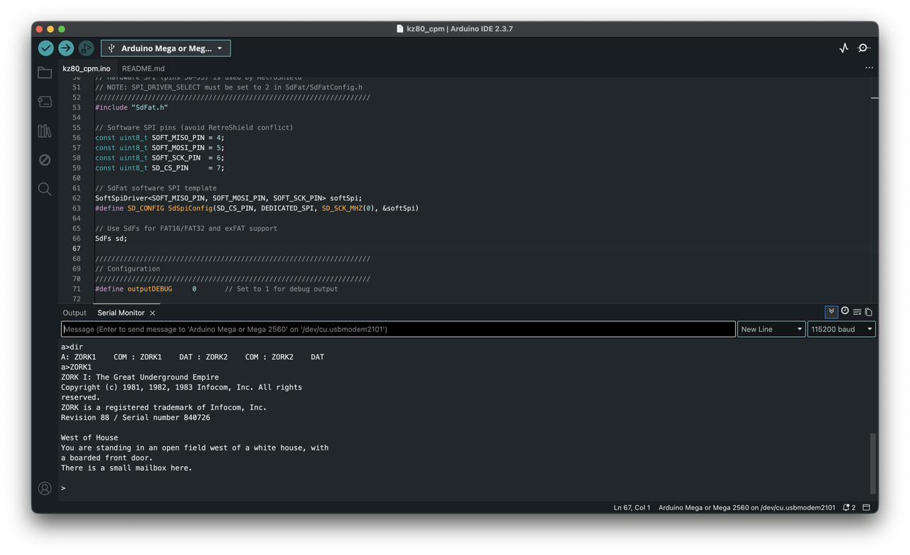
======================================
RetroShield Z80 CP/M 2.2
======================================

KDRAM2560:  OK (1MB DRAM)
SD Card:    OK (Software SPI)
Loading boot.bin...
Loaded 331 bytes to DRAM at 0x0000
Starting Z80...

RetroShield Z80 Boot Loader
Copyright (c) 2025 Alex Jokela, tinycomputers.io

Loading CPM.SYS.....................................................
Boot complete.


RetroShield CP/M 2.2
56K TPA

A>DIR
A: ZORK1    COM : ZORK1    DAT : ZORK2    COM : ZORK2    DAT
A>ZORK1

ZORK I: The Great Underground Empire
Copyright (c) 1981, 1982, 1983 Infocom, Inc. All rights reserved.
ZORK is a registered trademark of Infocom, Inc.
Revision 88 / Serial number 840726

West of House
You are standing in an open field west of a white house, with a boarded
front door.
There is a small mailbox here.

>
There's something deeply satisfying about this. The Z80 CPU running this game is the same architecture that ran it in 1981. The actual opcodes being executed are identical. We've just swapped floppy drives for SD cards and CRT terminals for USB serial.
The CPU Tick Loop: Where It All Comes Together
The heart of the system is the cpu_tick() function - called continuously in loop(), it handles one Z80 clock cycle:
inline __attribute__((always_inline))
void cpu_tick() {
    // Check for serial input
    if (Serial.available()) {
        reg6850_STATUS |= 0x01;  // Set RDRF
    }

    CLK_HIGH;  // Rising clock edge
    uP_ADDR = ADDR;  // Capture address bus

    // Memory access?
    if (!STATE_MREQ_N) {
        if (!STATE_RD_N) {
            // Memory read - get byte from DRAM
            DATA_DIR = DIR_OUT;
            DATA_OUT = DRAM.read8((unsigned long)uP_ADDR);
        }
        else if (!STATE_WR_N) {
            // Memory write - store byte to DRAM
            DRAM.write8((unsigned long)uP_ADDR, DATA_IN);
        }
    }
    // I/O access?
    else if (!STATE_IORQ_N) {
        if (!STATE_RD_N && prevIORQ) {
            // I/O read
            DATA_DIR = DIR_OUT;
            if (sd_handles_port(ADDR_L)) {
                prevDATA = sd_read_port(ADDR_L);
            }
            else if (ADDR_L == ADDR_6850_DATA) {
                prevDATA = Serial.read();
            }
            else if (ADDR_L == ADDR_6850_CONTROL) {
                prevDATA = reg6850_STATUS;
            }
            DATA_OUT = prevDATA;
        }
        else if (!STATE_WR_N && prevIORQ) {
            // I/O write
            DATA_DIR = DIR_IN;
            if (sd_handles_port(ADDR_L)) {
                sd_write_port(ADDR_L, DATA_IN);
            }
            else if (ADDR_L == ADDR_6850_DATA) {
                Serial.write(DATA_IN);
            }
        }
    }

    prevIORQ = STATE_IORQ_N;
    CLK_LOW;  // Falling clock edge
    DATA_DIR = DIR_IN;
}
This runs at roughly 100kHz - slow by modern standards, but plenty fast for interactive programs. The Z80 was designed for clock speeds of 2-4MHz, so we're running at about 3-5% of original speed. Text adventures don't mind.
The BIOS: Hardware Abstraction in 1KB
The CP/M BIOS is where the magic happens. It's the only part of CP/M that needs to be written for each new hardware platform. The BDOS and CCP are universal - they work on any machine with a conforming BIOS.
Our BIOS implements 17 entry points:
                org     BIOS_BASE       ; 0xF600

                jp      BOOT            ; 00 - Cold boot
WBOOTE:         jp      WBOOT           ; 03 - Warm boot
                jp      CONST           ; 06 - Console status
                jp      CONIN           ; 09 - Console input
                jp      CONOUT          ; 0C - Console output
                jp      LIST            ; 0F - List output
                jp      PUNCH           ; 12 - Punch output
                jp      READER          ; 15 - Reader input
                jp      HOME            ; 18 - Home disk
                jp      SELDSK          ; 1B - Select disk
                jp      SETTRK          ; 1E - Set track
                jp      SETSEC          ; 21 - Set sector
                jp      SETDMA          ; 24 - Set DMA address
                jp      READ            ; 27 - Read sector
                jp      WRITE           ; 2A - Write sector
                jp      LISTST          ; 2D - List status
                jp      SECTRAN         ; 30 - Sector translate
The most complex routines are the disk operations. READ and WRITE must calculate the byte offset within the disk image from track and sector numbers:
CALC_OFFSET:
        ; offset = (track * 26 + sector) * 128
        ld      hl, (TRACK)
        ld      de, 26          ; Sectors per track
        call    MULT16          ; HL = track * 26
        ld      de, (SECTOR)
        add     hl, de          ; HL = track * 26 + sector

        ; Multiply by 128 (shift left 7 times)
        xor     a               ; Clear carry byte
        add     hl, hl          ; *2
        adc     a, 0
        add     hl, hl          ; *4
        adc     a, a
        ; ... continue shifting ...

        ld      (SEEKPOS), hl
        ld      (SEEKPOS+2), a  ; 24-bit result
        ret
The Disk Parameter Block (DPB) tells CP/M about our disk geometry:
DPB:
        defw    26              ; SPT - sectors per track
        defb    3               ; BSH - block shift (1K blocks)
        defb    7               ; BLM - block mask
        defb    0               ; EXM - extent mask
        defw    242             ; DSM - total blocks - 1
        defw    63              ; DRM - directory entries - 1
        defb    0xC0            ; AL0 - allocation bitmap
        defb    0x00            ; AL1
        defw    16              ; CKS - checksum size
        defw    2               ; OFF - reserved tracks
These parameters define a standard 256KB 8-inch floppy format - the same format used by countless CP/M machines in the late 1970s.
Understanding CP/M's Memory Model
CP/M's memory layout is elegantly simple. The entire operating system fits in the top 8KB of the 64KB address space:
┌───────────────────────────────────────┐ 0xFFFF
│              BIOS                     │ ~1KB - Hardware abstraction
├───────────────────────────────────────┤ 0xF600
│              BDOS                     │ ~3.5KB - File system, I/O
├───────────────────────────────────────┤ 0xE800
│              CCP                      │ ~2KB - Command processor
├───────────────────────────────────────┤ 0xE000
│                                       │
│                                       │
│              TPA                      │ ~56KB - Your programs!
│     (Transient Program Area)          │
│                                       │
│                                       │
├───────────────────────────────────────┤ 0x0100
│          Page Zero                    │ 256 bytes - System variables
└───────────────────────────────────────┘ 0x0000
Page Zero contains crucial system information:
-
0x0000-0x0002: Jump to warm boot -
0x0005-0x0007: Jump to BDOS entry -
0x005C: Default FCB (File Control Block) -
0x0080: Default DMA buffer / command tail
When you type ZORK1 at the command prompt, CP/M loads ZORK1.COM at address 0x0100 and jumps there. The program has nearly 56KB to work with - a luxurious amount of memory for 1970s software.
Debugging Tips
Getting CP/M running required extensive debugging. Here are some tips if you're attempting something similar:
Enable Debug Output
Set outputDEBUG to 1 in the Arduino sketch to see every I/O operation:
#define outputDEBUG 1
This prints every port read/write, which is invaluable for tracking down why the BIOS isn't finding files or why sectors are being read from wrong locations.
Check Your Directory Format
The most common issue I encountered was improperly formatted disk images. Use a hex editor to verify:
- Directory starts at offset 0x1A00 (6656 bytes)
- Empty entries have 0xE5 in byte 0, not 0x00
- Filenames are space-padded to 8 characters, extensions to 3
Verify DMA Addresses
If programs load but crash immediately, check that the DMA address is being set correctly. The BIOS must output both low and high bytes:
ld      a, l
out     (SD_DMA_LO), a
ld      a, h
out     (SD_DMA_HI), a
Watch for Register Clobbering
Z80 subroutine calls don't preserve registers by default. If your SELDSK routine returns garbage, check whether the OPENDISK helper is destroying HL before the return.
Performance Considerations
The system runs at approximately 100kHz - about 3% of the Z80's original 4MHz speed. This is limited by:
- Arduino loop overhead: Each
cpu_tick()call has function call overhead - DRAM access time: Software-controlled DRAM is slower than dedicated hardware
- Software SPI: Bit-banging SPI adds latency to disk operations
For interactive programs like text adventures, this is imperceptible. For computation-heavy tasks, you'd notice the slowdown. WordStar feels sluggish but usable; compiling code would test your patience.
Future optimizations could include:
- Assembly-optimized cpu_tick() routine
- Hardware SPI with a different pin arrangement
- Overclocking the Arduino (at your own risk)
Challenges and Solutions
Challenge 1: Pin Conflicts
The RetroShield claims the hardware SPI pins (50-53). Solution: software SPI on alternate pins. The SdFat library's SoftSpiDriver template makes this painless.
Challenge 2: Memory Refresh
DRAM needs refresh every few milliseconds or it loses data. Solution: the KDRAM2560 library uses Timer 1 interrupts to handle this transparently. The refresh happens in the background - you never need to think about it.
Challenge 3: Disk Image Format
CP/M expects 0xE5 (not 0x00) for empty directory entries. A disk image initialized to all zeros will confuse CP/M into displaying phantom files. Solution: the cpm_disk.py tool properly initializes the directory.
Challenge 4: 24-bit Seek Positions
Disk images are 256KB, requiring 18 bits to fully address. My initial 16-bit seek implementation couldn't access sectors past track 51. Solution: added a third seek port (0x19) for bits 16-23.
Challenge 5: SELDSK Return Value Bug
CP/M's BDOS expects SELDSK to return a pointer to the Disk Parameter Header in HL. My initial code calculated this pointer, then called OPENDISK which clobbered HL. Solution: push/pop HL around the OPENDISK call.
Getting Started: Bill of Materials
To build your own CP/M machine, you'll need:
| Item | Approximate Cost |
|---|---|
| Arduino Mega 2560 | $15-40 |
| Z80 RetroShield | $35 |
| KDRAM2560 | $20 |
| MicroSD Card Module | $5 |
| MicroSD Card (≤32GB FAT32) | $5-10 |
| Jumper wires | $5 |
| Total | ~$100-130 |
Files and Resources
The complete Arduino sketch and supporting files are available on GitHub:
- Arduino Sketch: kz80_cpm.ino
- Boot Loader Source: boot.asm
- BIOS Source: bios.asm
- Disk Image Tool: cpm_disk.py
Required libraries: - KDRAM2560 - 1MB DRAM library - SdFat - SD card with software SPI support
Conclusion
Building this system was a journey through computing history. CP/M's clean architecture - the separation of BIOS, BDOS, and CCP - made it possible to port a 45-year-old operating system to completely alien hardware in a matter of days. For a fascinating look at CP/M in its heyday, check out the Computer Chronicles episode on CP/M from 1984.
The Z80 doesn't know it's being fed clock pulses by an Arduino, that its memory is dynamic RAM on a shield, or that its "floppy drives" are files on an SD card. It just executes its opcodes, one after another, exactly as it did in 1978.
And somewhere in that stream of opcodes, a small mailbox waits west of a white house, just as it has for over four and a half decades.
>open mailbox
Opening the small mailbox reveals a leaflet.

>read leaflet
"WELCOME TO ZORK!

ZORK is a game of adventure, danger, and low cunning. In it you will
explore some of the most amazing territory ever seen by mortals..."
Welcome to the underground empire. The password is nostalgia, and the treasure is understanding how elegantly simple these early systems really were.