There's a particular kind of satisfaction in building something from specifications rather than from someone else's implementation. When you take timing diagrams and instruction tables and turn them into working code, you're not copying; you're reconstructing. Every decision about how to decode an opcode, how to handle the flag register's undocumented bits, how to sequence a block transfer instruction: these become deliberate choices, informed by the original engineering documents but filtered through genuine understanding of the problem.
This is the story of writing a complete Z80 emulator under clean room constraints, with the twist that the implementer is an LLM. I used Claude Code to write every line of C (the CPU core, the test suite, the system emulator) with a single, non-negotiable rule: no reference to existing Z80 emulator source code. The inputs were the Zilog Z80 CPU User Manual, my architectural plan, and the test ROMs to prove it works.
An important clarification on what "clean room" means here. The constraint was no existing emulator source code, not "only the official Zilog manual." The Z80's undocumented behaviors (the F3/F5 flag bits, IXH/IXL half-index registers, DDCB register copy side effects) aren't in Zilog's official documentation. They come from decades of community reverse-engineering documented in references like Sean Young's "The Undocumented Z80 Documented" and similar technical write-ups. Claude's training data includes this secondary documentation, and the clean room constraint didn't prohibit drawing on that knowledge; it prohibited referencing how other emulators implemented that knowledge. The distinction matters: a specification of behavior is not the same as someone else's code that implements it.
Why an LLM Clean Room?
The term "clean room" comes from the semiconductor and software industries, where it describes a development methodology designed to produce implementations that are legally and intellectually independent of existing ones. In the chip fabrication sense, it's a literal dust-free environment. In the software sense, it means building from specifications and documentation without ever examining existing implementations.
When an LLM writes code, there's always the question: is this implementation derived from the specification I gave it, or is it pattern-matching against emulator source code in its training data? This is the central tension of using AI for systems programming. An LLM has likely seen dozens of Z80 emulators during training. If you just ask it to "write a Z80 emulator," you'll get something that works, but you can't know whether it's an original implementation or a recombination of memorized code.
The clean room constraint changes the experiment. By explicitly instructing Claude that this is a clean room project (that all implementation must be derived solely from specifications and documentation, not from existing emulator source code), you're testing whether the model can work from first principles rather than from pattern recall. Can it read an instruction set specification, understand the semantics of each opcode, and produce correct flag computations without cribbing from someone else's z80.c?
Antirez explored this territory recently with his own Z80 emulator project, using Claude Code to generate a working ZX Spectrum emulator. His experiment demonstrated something important about LLM-assisted development: that providing an agent with proper specifications and documentation, rather than asking it to regurgitate training data, produces implementations that are genuinely novel assemblies of knowledge rather than memorized patterns. The code Claude produced for antirez passed the notoriously thorough ZEXALL test suite, validating every documented Z80 behavior including the undocumented flag bits. Antirez's conclusion was that the LLM wasn't decompressing training data; it was assembling knowledge, the way a human developer would when working from a datasheet.
Reading antirez's write-up was the catalyst for this project. I wanted to see whether the same approach (specifications in, working emulator out, clean room constraints enforced throughout) would hold up when I drove the process myself. The Z80 User Manual is one of the best-documented processor specifications ever written. Everything you need to build a working emulator is in that document. The question is whether an LLM, given that document as its source of truth and told not to reference existing implementations, can produce something correct.
The Process
The workflow looked nothing like "prompt and pray." I started by writing a detailed architectural plan: the CPU state struct layout, the instruction decoding strategy (bit field decomposition), the system emulator's responsibilities, the test coverage targets. This plan became Claude's specification, not just "write a Z80 emulator" but "implement the Z80 CPU using x/y/z/p/q bit field decoding of the opcode byte, with these specific callback interfaces, these T-state timing requirements, and this test structure."
Claude then implemented each component: z80.h first, then the full z80.c CPU core, then the test suite, then the system emulator. I reviewed each piece, ran the tests, identified failures, and fed the errors back. The first compile had a T-state timing issue with DD/FD prefixed instructions; the prefix overhead was being double-counted. One test out of 117 failed. Claude diagnosed the problem (the prefix dispatch was adding 4 T-states on top of instruction timings that already included the prefix cost) and fixed it.
This iterative loop (plan, implement, test, fix) is exactly how a human developer would work. The difference is velocity. The entire CPU core, all 1,300 lines of C covering every official Z80 instruction plus undocumented behaviors, was produced in a single session. A human developer working from the same specification would spend days or weeks reaching the same point. The LLM's advantage isn't that it knows more; it's that it can hold the entire instruction set specification in context and translate it to code without the cognitive overhead of context-switching between the manual and the editor.
The Architecture
What Claude produced is a four-file emulator:
| File | Purpose |
|---|---|
z80.h |
CPU state struct, flag constants, public API |
z80.c |
Complete Z80 CPU emulation core |
z80_test.c |
117 unit tests covering all instruction groups |
zxs.c |
Unified emulator binary with ACIA serial and CP/M support |
The design philosophy is straightforward: the CPU core knows nothing about the system it's running in. It communicates with the outside world exclusively through four callback functions: memory read, memory write, I/O in, and I/O out. The system emulator (zxs.c) provides these callbacks and implements whatever hardware peripherals the target system requires.
This separation matters. The same CPU core can run a Grant Searle BASIC SBC, an RC2014, or a CP/M program without any changes to z80.c. The system-specific behavior lives entirely in the callbacks.
The CPU State
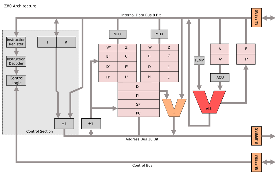
A Z80 has more programmer-visible state than you might expect if you're used to simpler processors. The main register file includes the accumulator A and flags register F, plus three general-purpose register pairs BC, DE, and HL. But then there's a complete shadow set of all those registers (A', F', BC', DE', HL'), accessible only through the EX AF,AF' and EXX exchange instructions.
Add the two 16-bit index registers IX and IY, the stack pointer SP, the program counter PC, the interrupt vector register I, and the memory refresh counter R, and you've got a substantial amount of state to track. Then there's the interrupt system: two flip-flops IFF1 and IFF2, the interrupt mode register (modes 0, 1, or 2), a halt flag, and a one-instruction delay flag for the EI instruction.
typedef struct {
    /* Main registers */
    uint8_t  A, F;
    uint8_t  B, C, D, E, H, L;

    /* Shadow registers */
    uint8_t  A_, F_, B_, C_, D_, E_, H_, L_;

    /* Index registers */
    uint16_t IX, IY;

    /* Stack pointer and program counter */
    uint16_t SP, PC;

    /* Interrupt and refresh registers */
    uint8_t  I, R;

    /* Interrupt state */
    uint8_t  IFF1, IFF2, IM, halted, ei_delay;

    /* Cycle counter */
    unsigned long t_states;

    /* Memory and I/O callbacks */
    z80_read_fn  mem_read;
    z80_write_fn mem_write;
    z80_in_fn    io_in;
    z80_out_fn   io_out;
    void *ctx;
} z80_t;
I chose to store each register as an individual byte rather than using unions or bitfields to form 16-bit pairs. This makes the code more explicit; when you see cpu->B, you know exactly what's being accessed. Register pairs are assembled and disassembled through inline helper functions like rp_bc() and set_bc(). The compiler optimizes these away completely, so there's no performance cost for the clarity.
Instruction Decoding: The Bit Field Approach
The Z80's instruction encoding has a structure that isn't immediately obvious if you're just looking at an opcode table, but becomes clear once you read the User Manual carefully. Every opcode byte can be decomposed into bit fields:
-
x= bits 7:6 (the two highest bits) -
y= bits 5:3 (the middle three bits) -
z= bits 2:0 (the lowest three bits) -
p= bits 5:4 (y >> 1) -
q= bit 3 (y & 1)
These fields determine the instruction's category and operands. For the unprefixed opcodes:
- x=0: Miscellaneous: relative jumps, 16-bit loads, 16-bit arithmetic, INC/DEC, 8-bit loads with immediate data, and the accumulator rotate/DAA/CPL/SCF/CCF group
-
x=1: Register-to-register loads (
LD r, r'), with the special case ofLD (HL),(HL)encodingHALTinstead -
x=2: ALU operations between the accumulator and a register (
ADD A,rthroughCP r) - x=3: Returns, jumps, calls, stack operations, RST vectors, I/O, exchange instructions, interrupt control, and the prefix bytes for extended instruction groups
This structure means you can decode most unprefixed instructions with a three-level switch on x, then z (or y), rather than a 256-entry lookup table. The code reads more like the specification:
switch (x) {
case 1:
    if (y == 6 && z == 6) {
        /* HALT */
        c->halted = 1;
        c->PC--;
    } else {
        /* LD r[y], r[z] */
        set_reg8(c, y, get_reg8(c, z));
    }
    break;

case 2:
    /* ALU A, r[z] */
    do_alu(c, y, get_reg8(c, z));
    break;
The register index mapping (0=B, 1=C, 2=D, 3=E, 4=H, 5=L, 6=(HL), 7=A) is used consistently throughout the instruction set. Index 6 always means the memory byte pointed to by HL, which is why LD (HL),(HL) would be meaningless (load memory from the same memory location) and gets repurposed as HALT.
The Prefix System
The Z80 extends its instruction set through prefix bytes: CB, ED, DD, and FD. Each opens up a different dimension of functionality.
CB prefix: Rotate/shift operations and bit manipulation. The same x/y/z decode applies, but now x=0 is rotate/shift, x=1 is BIT (test), x=2 is RES (reset), and x=3 is SET. This gives you eight different rotate/shift operations on any of the eight register positions, and bit test/set/reset for any of eight bit positions on any register. That's 248 instructions from a single prefix byte.
ED prefix: Extended operations that don't fit the main opcode map. Block transfer and search instructions (LDI, LDIR, LDD, LDDR, CPI, CPIR, and their output counterparts), 16-bit arithmetic with carry (ADC HL,rp and SBC HL,rp), extended I/O (IN r,(C) and OUT (C),r), interrupt mode selection, and a handful of register transfer instructions (LD I,A, LD A,R, etc.).
DD and FD prefixes: These modify the following instruction by replacing HL with IX or IY respectively. Wherever the unprefixed instruction uses HL as a 16-bit register, the prefixed version uses IX or IY. Wherever it accesses (HL) as a memory operand, the prefixed version accesses (IX+d) or (IY+d), where d is a signed displacement byte inserted between the opcode and any immediate data.
This substitution extends to the individual H and L registers in many contexts. LD A,H becomes LD A,IXH with a DD prefix. These "half-index" register operations are technically undocumented but universally supported by real silicon and widely used by software. A clean room implementation needs to handle them.
DDCB and FDCB: The most complex prefix combination. For bit operations on indexed memory (IX+d), the displacement byte comes before the opcode byte, not after:
DD CB d op → operation on (IX+d)
This reversed order exists because the Z80's internal pipeline needs the displacement early to begin the memory access while decoding the operation. It's an elegant microarchitectural optimization that reveals itself in the instruction encoding.
There's an additional subtlety: undocumented behavior where DDCB/FDCB rotate and set/reset operations also copy their result into a register specified by the z field of the opcode. RLC (IX+5) with a z field of 0 also loads the result into B. This behavior is consistent across all real Z80 chips and is relied upon by some software.
The ALU
The eight ALU operations (ADD, ADC, SUB, SBC, AND, XOR, OR, CP) share a common pattern in how they affect the flags register. Getting the flags right is the single most important aspect of Z80 emulation, and the area where most subtle bugs hide.
The Z80's flag register contains eight bits, six of which are documented:
| Bit | Name | Meaning |
|---|---|---|
| 7 | S | Sign (copy of bit 7 of result) |
| 6 | Z | Zero (result is zero) |
| 5 | F5 | Undocumented (copy of bit 5 of result*) |
| 4 | H | Half-carry (carry from bit 3 to bit 4) |
| 3 | F3 | Undocumented (copy of bit 3 of result*) |
| 2 | P/V | Parity (logic ops) or Overflow (arithmetic ops) |
| 1 | N | Subtract (set if last operation was subtraction) |
| 0 | C | Carry (carry out of bit 7) |
The asterisk on F3 and F5 matters. For most operations, bits 3 and 5 come from the result. But for CP (compare), they come from the operand, not the result. This is because CP is internally a subtraction that discards the result and keeps only the flags, but the Z80 designers connected the F3 and F5 flag inputs to the operand bus rather than the internal result bus for this particular instruction. It's the kind of detail that only shows up when you're testing against real hardware behavior.
The overflow flag computation deserves special attention. For addition, overflow occurs when two operands of the same sign produce a result of the opposite sign:
uint8_t v = ((a ^ val ^ 0x80) & (a ^ result)) & 0x80;
For subtraction, overflow occurs when two operands of different signs produce a result whose sign differs from the first operand:
uint8_t v = ((a ^ val) & (a ^ result)) & 0x80;
These one-liners replace what would otherwise be multi-branch conditional logic. They work because XOR detects sign differences, and AND combines the two conditions.
Block Operations
The Z80's block instructions are one of its most powerful features and one of the trickiest to implement correctly. LDIR (Load, Increment, Repeat) copies a block of memory from the address in HL to the address in DE, decrementing BC as a counter, and repeating until BC reaches zero.
The implementation requires careful attention to the repeat mechanism. When BC is not yet zero, LDIR decrements PC by 2 so that the next instruction fetch re-executes the same LDIR opcode. The repeated iteration takes 21 T-states; the final iteration (when BC reaches zero) takes only 16 T-states. This asymmetry matters for cycle-accurate emulation:
case 0: /* LDI/LDD/LDIR/LDDR */
    {
        uint8_t val = rb(c, rp_hl(c));
        wb(c, rp_de(c), val);
        /* Increment or decrement based on instruction */
        if (y == 4 || y == 6) {
            set_hl(c, rp_hl(c) + 1);
            set_de(c, rp_de(c) + 1);
        } else {
            set_hl(c, rp_hl(c) - 1);
            set_de(c, rp_de(c) - 1);
        }
        set_bc(c, rp_bc(c) - 1);
        /* ... flag computation ... */
        if (y >= 6 && rp_bc(c) != 0) {
            c->PC -= 2;
            repeat = 1;
        }
    }
    return repeat ? 21 : 16;
The flag behavior during block operations is another area where the specification requires careful reading. The P/V flag reflects whether BC is non-zero after the decrement, acting as a "more data" indicator. The undocumented F3 and F5 flags come from the sum of the transferred byte and the accumulator, with F5 derived from bit 1 rather than bit 5 of that sum. These details are well-documented in the secondary literature but require careful implementation.
The search variants (CPI, CPIR, etc.) are even more nuanced. They compare the accumulator against memory, set Z if a match is found, and terminate on either a match or BC reaching zero. The flags after a search operation encode both whether a match was found and whether the counter has been exhausted, two independent pieces of information packed into the flag register.
T-State Timing
Every Z80 instruction has a specific T-state (clock cycle) count that's documented in the User Manual. For an emulator driving a simulated UART or polling for terminal input at realistic intervals, accurate timing is essential.
The timing model uses a simple accumulator. Each call to z80_step() returns the number of T-states consumed and adds them to a running total in the CPU state. The system emulator uses this to determine when to poll for input or deliver interrupts:
while (!quit_flag) {
    unsigned long target = cpu.t_states + 7373;
    while (cpu.t_states < target) {
        z80_step(&cpu);
    }
    /* Poll for serial input, deliver interrupts */
}
The value 7373 represents approximately 2 milliseconds at 3.6864 MHz, the crystal frequency used by many Z80 SBC designs. This frequency was chosen historically because it divides cleanly to produce standard baud rates. At 9600 baud with 10 bits per character (start, 8 data, stop), you get approximately 960 characters per second, or about one character every 3,840 clock cycles. Polling at 7373-cycle intervals gives roughly two opportunities to check for input per character time, enough for reliable serial communication without excessive overhead.
Conditional instructions have different cycle counts depending on whether the condition is met. A JR Z,d takes 12 T-states when the jump is taken but only 7 when it falls through. CALL cc,nn takes 17 T-states when taken, 10 when not. These differences reflect the real pipeline behavior of the Z80; a taken branch requires additional cycles to flush the prefetch and load the new address.
The Interrupt System
The Z80 supports three interrupt modes and a non-maskable interrupt. Mode 1 is the simplest and most commonly used in SBC designs: a maskable interrupt causes the CPU to push the current PC and jump to address 0x0038, just like an RST 38h instruction.
Mode 2 is more sophisticated. The interrupting device places a vector byte on the data bus, which is combined with the I register to form a 16-bit address into a vector table in memory. The CPU reads the actual interrupt service routine address from that table location. This provides up to 128 different interrupt vectors, enabling complex multi-device interrupt schemes.
The EI instruction has a subtle but critical behavior: it doesn't enable interrupts immediately. Instead, it sets a one-instruction delay, so the next instruction after EI executes before any pending interrupt can be serviced. This guarantees that EI; RETI (enable interrupts, then return from interrupt) executes atomically; the return completes before any new interrupt can preempt it.
case 7: /* EI */
    c->IFF1 = 1;
    c->IFF2 = 1;
    c->ei_delay = 1;
    break;
And in the interrupt handler:
void z80_interrupt(z80_t *cpu, uint8_t data) {
    if (!cpu->IFF1 || cpu->ei_delay) return;
    /* ... process interrupt ... */
}
DAA: The Most Misunderstood Instruction
DAA (Decimal Adjust Accumulator) is arguably the Z80's most complex single instruction. It adjusts the result of a previous addition or subtraction to produce a valid BCD (Binary-Coded Decimal) result. The adjustment depends on three pieces of state: the current value of the accumulator, the carry flag, and the half-carry flag. It also behaves differently depending on whether the previous operation was addition or subtraction (tracked by the N flag).
The algorithm: if the lower nibble exceeds 9 or the half-carry flag is set, add (or subtract) 0x06. If the upper nibble exceeds 9 or the carry flag is set, add (or subtract) 0x60. Update carry if the upper correction was applied.
static void daa(z80_t *c) {
    uint8_t a = c->A;
    uint8_t correction = 0;
    uint8_t carry = c->F & Z80_CF;

    if ((c->F & Z80_HF) || (a & 0x0F) > 9)
        correction |= 0x06;
    if (carry || a > 0x99) {
        correction |= 0x60;
        carry = Z80_CF;
    }

    if (c->F & Z80_NF)
        c->A -= correction;
    else
        c->A += correction;

    c->F = sz53p(c->A) | carry | (c->F & Z80_NF) |
           ((a ^ c->A) & Z80_HF);
}
BCD arithmetic was important in the era when the Z80 was designed. Financial calculations, display drivers, and industrial controllers all needed decimal precision without floating-point hardware. The Z80's DAA instruction made BCD arithmetic practical on an 8-bit processor by adjusting binary results back into valid decimal digits after each operation.
Testing: 117 Ways to Be Wrong
Writing a test suite for a CPU emulator is an exercise in paranoia. Every instruction has multiple paths through the flag logic, multiple edge cases in operand handling, and multiple interactions with the rest of the CPU state. The test suite covers:
- Register loads: 8-bit immediate, register-to-register, 16-bit immediate, indirect through BC/DE/HL, absolute addressing, HL indirect
- 8-bit ALU: All eight operations with basic values, carry/borrow propagation, overflow detection, half-carry, undocumented flag bits
- 16-bit arithmetic: ADD HL with carry, SBC HL, ADC HL
- INC/DEC: 8-bit with overflow and half-carry edge cases, 16-bit wrapping
- Rotates and shifts: RLCA/RRCA/RLA/RRA (accumulator), CB-prefixed RLC/RRC/RL/RR/SLA/SRA/SRL on registers
- BIT/SET/RES: Test, set, and reset individual bits
- Jumps and branches: JP, JR, DJNZ with taken/not-taken paths
- Calls and returns: CALL/RET with condition codes, RST vectors
- Stack operations: PUSH/POP for all register pairs including AF
- Block operations: LDI/LDIR/LDD, CPI/CPIR, INI/OUTI
- Exchange instructions: EX AF, EXX, EX DE,HL, EX (SP),HL
- Interrupt system: IM modes, Mode 1 and Mode 2 dispatch, NMI, EI delay
- IX/IY indexed: Loads, stores, arithmetic, IXH/IXL access, DDCB bit operations
- T-state timing: Verified counts for representative instructions from each group
- R register: Increment behavior, bit 7 preservation
Each test sets up a specific CPU state, loads a short instruction sequence into memory, executes it, and verifies the results. The test framework is minimal, just macros for assertions and a runner that reports pass/fail:
Z80 CPU Test Suite
==================
test_nop                                                    PASS
test_ld_reg_imm                                             PASS
...
test_r_bit7_preserved                                       PASS

==================
Results: 117/117 passed
All 117 pass. But passing unit tests isn't the same as passing real software. The real validation comes from booting actual ROMs.
The System Emulator
The zxs binary wraps the CPU core with enough peripheral emulation to run two classes of software: Grant Searle-style BASIC SBCs with ACIA serial I/O, and CP/M .COM programs with a minimal BDOS shim.
ACIA Serial Emulation
The Motorola MC6850 ACIA (Asynchronous Communications Interface Adapter) is the serial chip used in the Grant Searle Z80 SBC design and many similar projects. It presents two registers to the CPU:
- Status register (base address): Bit 0 = Receive Data Register Full (RDRF), Bit 1 = Transmit Data Register Empty (TDRE)
- Data register (base + 1): Read for received data, write to transmit
The emulation maps these to terminal I/O. TDRE is always set (the "transmitter" is always ready since we're writing directly to stdout). RDRF is set when non-blocking read() has captured a character from stdin. The ACIA's interrupt capability is emulated: when receive interrupts are enabled and data is available, the emulator delivers an RST 38h interrupt to the CPU.
Serial Port Auto-Detection
Rather than hardcoding the ACIA port address, the emulator scans the loaded ROM for IN A,(n) (DB xx) and OUT (n),A (D3 xx) instruction patterns. It collects the referenced port addresses and looks for adjacent pairs (status + data ports) that have both IN and OUT references, the signature of a serial peripheral. For the Grant Searle ROM, this reliably detects port base 0x80. For ROMs that use different port configurations, a --port flag provides a manual override.
CP/M Mode
For .com and .cim files, the emulator switches to CP/M mode: the program is loaded at 0x0100, the stack pointer is set to 0xFFFE with a return address of 0x0000 pushed, and BDOS calls are intercepted at address 0x0005. Only the essential BDOS functions are implemented (console output (function 2) and string output (function 9)), but this is enough to run many CP/M utilities and test programs.
System Auto-Detection
File extension determines the system type: .com and .cim files run in CP/M mode, everything else runs as a BASIC SBC. Intel HEX files are detected and parsed regardless of extension. The --system flag overrides auto-detection when needed.
Booting BASIC
The real test of any emulator is whether it runs real software. Here's what happens when you point zxs at Grant Searle's BASIC ROM:
$ ./zxs basic.rom
Loaded 8192 bytes at 0x0000
BASIC SBC mode, serial port base: 0x80 (Ctrl+] to exit)
Z80 SBC By Grant Searle

Memory top?
That banner, "Z80 SBC By Grant Searle," represents thousands of Z80 instructions executing correctly. The ROM initializes memory, configures the ACIA, sets up the interrupt handler, and enters the BASIC interpreter's command loop. Each of those steps exercises a different subset of the CPU's instruction set. A single incorrectly implemented instruction (a wrong flag bit, a miscounted displacement, a botched stack operation) would cause the ROM to crash or produce garbage output.
The RC2014 BASIC ROM boots as well, though it requires specifying the serial port base since its ROM references multiple I/O addresses:
$ ./zxs --port 0x80 rc2014_56k.hex
Loaded 8154 bytes from HEX file
BASIC SBC mode, serial port base: 0x80 (Ctrl+] to exit)

RC2014 - MS Basic Loader
z88dk - feilipu

Memory top?
Intel HEX file loading is handled transparently. The emulator detects the format by checking for the : record marker and parses the standard Intel HEX record format (data records, EOF records, address fields, checksums).
What I Learned About LLM Clean Room Development
This project taught me as much about working with LLMs as it did about the Z80. Some observations:
Specification quality determines output quality. When I gave Claude a vague instruction like "implement the Z80," the result would have been a generic emulator shaped by whatever training data dominates. When I gave it a detailed architectural plan (bit field decoding, specific callback interfaces, T-state requirements), the result was a coherent, well-structured implementation that reflected the design decisions in the specification. Antirez observed the same thing: the LLM performs dramatically better when you provide documentation and constraints rather than open-ended prompts.
LLMs can work from datasheets, not just from memory. The clean room constraint was the whole point: could Claude produce correct Z80 flag behavior, proper DDCB/FDCB displacement ordering, accurate block operation semantics, all derived from specification knowledge rather than memorized source code? The 117 passing tests and booting ROMs suggest it can. The code doesn't look like any particular existing emulator. The bit field decoder, the ALU structure, the prefix dispatch: these are architecturally reasonable but stylistically original.
The bug pattern was illuminating. The one test failure in the initial implementation was a T-state timing issue: DD/FD prefix overhead was being double-counted. This is exactly the kind of bug a human developer would make when implementing prefix dispatch, a bookkeeping error at the boundary between the prefix handler and the main decoder. It was not the kind of error you'd see from copying existing code, where the timing would already be correct. The bug was original, which paradoxically increases confidence that the implementation is too.
The Z80's instruction encoding is remarkably systematic. Once you express the x/y/z/p/q bit field decomposition in the architectural plan, the entire instruction set becomes a small number of patterns applied consistently across register indices and operation codes. Claude picked up on this structure immediately and produced a decoder that reads like the specification. The elegance of Zilog's encoding is invisible in an opcode table but obvious in a decoder, and an LLM can see that structure when pointed at it.
The DD/FD prefix system is essentially a register renaming mechanism. It doesn't introduce new operations; it modifies existing ones by replacing HL with IX or IY. Expressing this in the plan as "replace HL→IX/IY, H→IXH/IYH, L→IXL/IYL, (HL)→(IX+d)/(IY+d)" gave Claude the conceptual framework to implement DD/FD support as a modifier on the existing decoder rather than duplicating 200+ instruction handlers.
Flag behavior is the specification. Two Z80 emulators can produce identical results for every instruction and still differ in their flag register output. The undocumented F3 and F5 bits, the special CP flag behavior, the block instruction flag computations: these are what distinguish a correct emulator from an approximately correct one. Claude got the CP flag anomaly right (F3/F5 from the operand, not the result), which suggests it was working from specification knowledge about the Z80's internal bus routing rather than just copying a known-good flag computation.
Clean room constraints make LLM output more trustworthy, not less. There's an irony here: by restricting what the LLM can reference, you get more confidence in the result. If Claude had produced code that looked suspiciously like MAME's Z80 core, you'd wonder whether it was simply reciting training data. Instead, it produced an implementation that's structurally sound, stylistically distinct, and correct, the hallmarks of working from specifications rather than from examples.
The Code
The complete source is on GitHub, five files totaling roughly 3,000 lines of C. It builds with make, produces zero warnings with -Wall -Wextra, and runs Grant Searle and RC2014 BASIC ROMs out of the box.
$ make
cc -Wall -Wextra -O2 -o zxs zxs.c z80.c
cc -Wall -Wextra -O2 -o z80_test z80_test.c z80.c

$ ./z80_test
Z80 CPU Test Suite
==================
...
Results: 117/117 passed

$ ./zxs basic.rom
Z80 SBC By Grant Searle
Memory top?
There is more to do. ZEXALL compliance would be the next validation milestone; it tests every instruction against known-good results captured from real Z80 hardware. ZX Spectrum emulation would require adding ULA video, keyboard matrix scanning, and Spectrum-specific memory banking. Cycle-exact timing would enable accurate sound emulation and demo-scene effects.
But for now, the ROM boots, BASIC runs, and every line of the emulator traces back to Z80 specifications and documentation rather than someone else's z80.c. An LLM wrote it, but a human designed it, constrained it, tested it, and validated it against real hardware ROM images. The clean room constraint didn't just produce a trustworthy emulator; it produced a trustworthy process for using LLMs on systems programming tasks. Give the model a specification instead of an open-ended prompt. Enforce constraints that prevent training data regurgitation. Validate against real-world artifacts, not just unit tests.
Antirez asked whether LLMs create original code or decompress training data. This project is one more data point on the side of original creation, but only when you set up the conditions for it. The clean room is what makes the difference.