The Forth programming language was developed in the late 1960s by Charles H. Moore as a stack-oriented language that would allow efficient data manipulation and rapid program development. One of its most distinctive features is the dual-stack architecture, where a parameter stack is used for data passing and a return stack manages control flow. This unique design made Forth an excellent fit for the microprocessor architectures that emerged in the 1970s, most notably the Z80.
 The Z80 microprocessor, introduced in 1976 by Zilog, has an architecture that pairs well with Forth, particularly because of its efficient use of memory and registers. A typical Forth environment on the Z80 is initialized through a kernel, written in Z80 assembly language, which serves as the foundational layer. Upon this base, high-level Forth "words" or function calls are constructed, broadening the language's capabilities. Users can further extend these capabilities by defining their own "words" through a system called "colon definitions." The resulting definitions are stored in Forth's dictionary, a data structure that allows for quick look-up and execution of these custom words.
For hardware interfacing, the Z80 microprocessor's built-in support for memory-mapped I/O is an advantage that complements Forth's intrinsic ability for direct hardware manipulation. Forth’s language primitives enable direct interaction with specific memory locations, facilitating control over connected hardware components. This hardware-level control is indispensable for applications like real-time control systems or embedded applications. In this context, the Z80's specific features, such as its set of index registers and bit manipulation instructions, are highly beneficial.
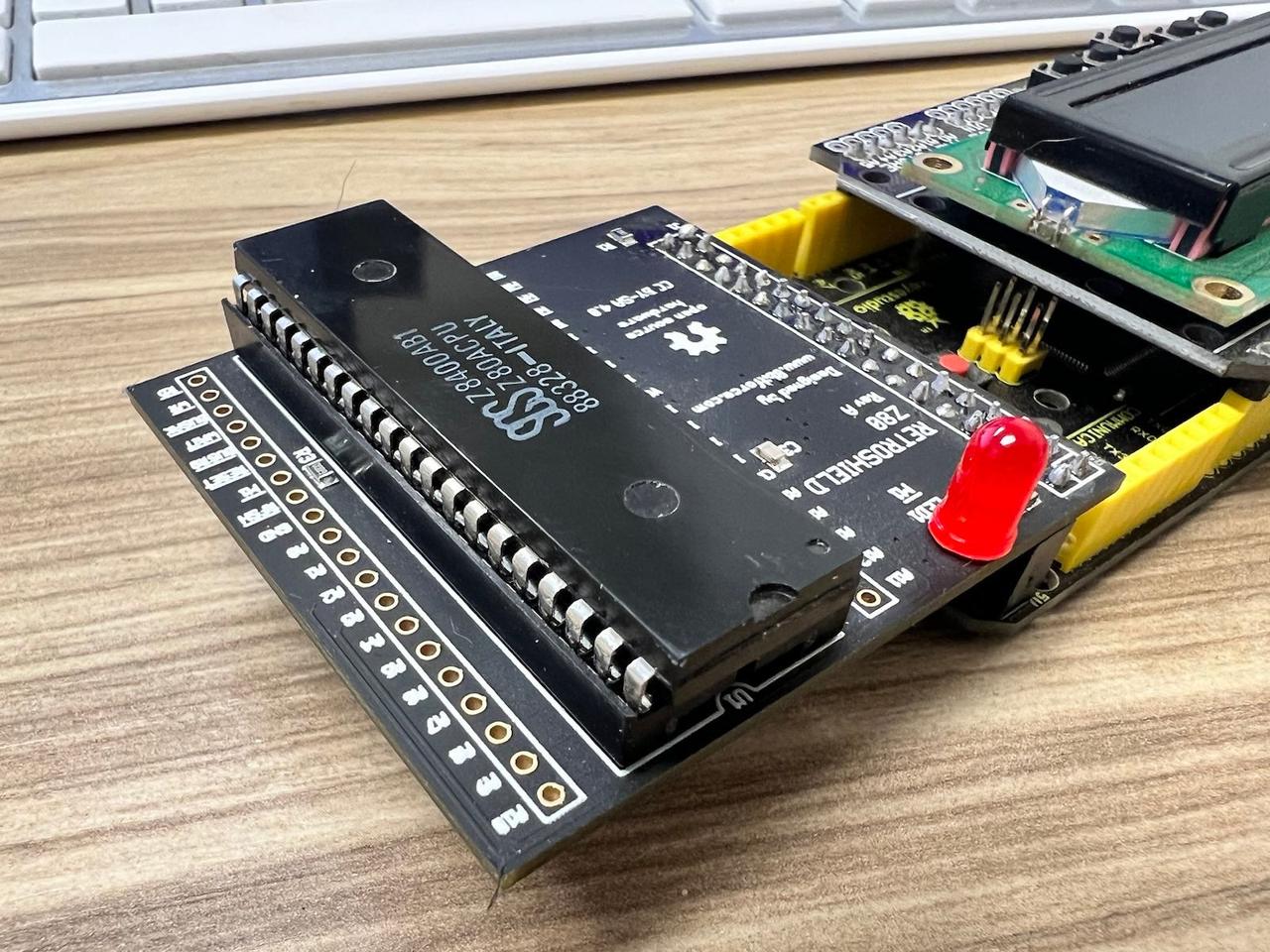
On top of the core Forth environment, specialized versions have been developed exclusively for the Z80. One such environment is Firth, a Z80-centric Forth variant by John Hardy, which is optimized for retrocomputing applications. For our project, we'll be deploying Firth in conjunction with Retroshield Z80, a Z80 ⇄ Arduino Mega bridge that allows the execution of Z80 instructions while emulating certain hardware components in Arduino code.
A unique feature of Forth is its dual functionality as both an interpreter and a compiler provides a valuable toolset for various application scenarios. In interpreter mode, users can execute code interactively, which is ideal for real-time debugging and incremental code testing. On the other hand, the compiler mode employs a single-pass approach, generating optimized executable code with minimal overhead. This design is particularly crucial in resource-constrained environments that require quick code iterations and minimal execution time.
While Forth may not execute as quickly as pure assembly language, its benefits often outweigh this shortcoming. For instance, the language offers structured control flow constructs like loops and conditionals, which are not inherently present in assembly. It also has a unified parameter passing mechanism via its dual-stack architecture, making it more manageable and readable than equivalent assembly code. These features make Forth an efficient option in scenarios where resources are limited but performance and functionality cannot be compromised.
The Z80's architecture, with its index registers and bit manipulation instructions, enables an additional level of optimization when used with Forth. Such low-level hardware functionalities can be directly accessed and manipulated through Forth's high-level words, offering a blend of ease-of-use and performance. These technical synergies between the Z80's architecture and Forth's language design make it a compelling choice for embedded systems and other hardware-centric applications. This tight coupling between hardware and software functionalities enables developers to construct highly efficient, tailored solutions for complex computational problems.
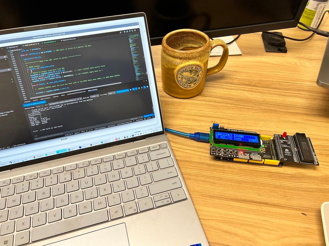
Firth on the RetroShield Z80
Configuration:
==============
Debug:      1
LCD-DISP:   1
SPI-RAM:    0 Bytes
SRAM Size:  6144 Bytes
SRAM_START: 0x2000
SRAM_END:   0x37FF


Firth - a Z80 Forth by John Hardy


>
---- Sent utf8 encoded message: ": iterate begin over over > while dup . 1+ repeat drop drop ;\n" ----
: iterate begin over over > while dup . 1+ repeat drop drop ;


>
---- Sent utf8 encoded message: "25 1 iterate\n" ----
25 1 iterate

1 2 3 4 5 6 7 8 9 10 11 12 13 14 15 16 17 18 19 20 21 22 23 24
>
RetroShield Z80
The RetroShield Z80 functions as a hardware emulator for the Z80 microprocessor by interfacing with an Arduino Mega. The Arduino Mega handles the simulation of memory and I/O ports, utilizing its multiple GPIO pins to emulate the Z80's address, data, and control buses. Clock speed synchronization between the Z80 and Arduino Mega is essential to ensure precise timing for software instruction execution.
Emulated memory configurations are provided via the Arduino Mega, mapping directly into the Z80's accessible address space. Due to hardware limitations on the Arduino, the size of the emulated memory is constrained but generally sufficient for most retrocomputing tasks. Specialized software environments such as Firth, a Forth implementation tailored for the Z80, can be executed. Direct memory access and hardware interaction are among the functionalities that RetroShield Z80 offers.
The emulation logic is generally implemented in software that runs on the Arduino Mega, and the Z80-specific code can be developed independently. Once the Z80 code is compiled into a binary or hex format, it can be loaded into the emulated memory. This approach expedites development cycles by facilitating the simultaneous handling of both emulation and Z80-specific software without the need to switch between different hardware setups for coding and debugging.
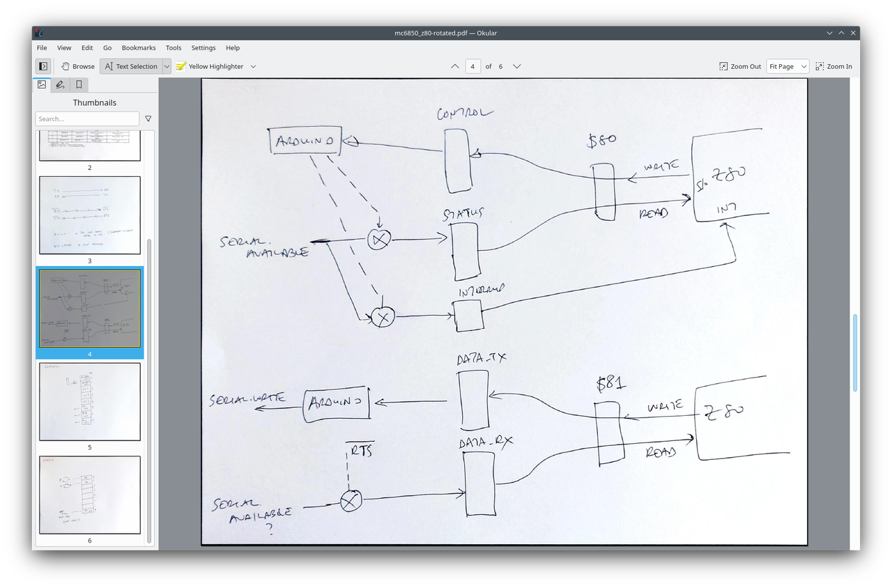
Retroshield ⇄ Arduino Mega Data Flow
While Firth can run on it without any major issues, the system is not entirely plug-and-play when it comes to serial communications. The heart of the problem lies in the difference in hardware expectations between the Retroshield's existing software and Firth's architecture and implementation. Current software solutions tailored for the Retroshield often operate under the assumption that an Intel 8251 USART will handle serial communications. However, Firth is engineered to work with the Motorola 6850 ACIA.
In order to use Firth with the Retroshield, our first task is to replace the Intel 8251 USART emulation code with Motorola 6850 ACIA emulation code. The Intel 8251 has a simpler register structure, featuring just two primary registers, STATE and MODE. These are essential for controlling various functionalities of the device, including data flow and operational mode settings. On the other hand, the Motorola 6850 ACIA comes with a more complex set of four registers: DATA RX for data reception, DATA TX for data transmission, CONTROL for configuring the device, and STATUS for monitoring various operational conditions.
Setting the Stage with Definitions and Initialization
Our code starts by setting up environment, defining memory-mapped addresses and control registers essential for the UART's operation. Memory-mapped addresses enable the CPU to interact directly with peripheral devices, like our UART in this case.
#define ADDR_6850_DATA        0x81
#define ADDR_6850_CONTROL     0x80
#define CONTROL_RTS_STATE     (reg6850_CONTROL & 0b01000000)
#define CONTROL_TX_INT_ENABLE (reg6850_CONTROL & 0b00100000)
#define CONTROL_RX_INT_ENABLE (reg6850_CONTROL & 0b10000000)
These constants create an abstraction layer that allows you to interact with the UART as if it were part of the CPU's own memory.
Internal Registers and Initialization
Following the addresses, internal registers (reg6850_DATA_RX, reg6850_DATA_TX, etc.) are initialized. A specialized function, mc6850_init(), is employed to set the UART's initial state. The method of doing this is straightforward but crucial: each bit in the control and status registers controls a particular feature of the UART.
void mc6850_init() {
  // Initialize the 6850 UART settings here
  reg6850_DATA_RX    = 0x00;
  reg6850_DATA_TX    = 0x00;
  reg6850_CONTROL    = 0b01010100;  // RTS HIGH, TX INT Disabled, RX INT Disabled, 8n1, Divider by 1
  reg6850_STATUS     = 0b00000010;  // CTS LOW, DCD LOW, TX EMPTY 1, RX FULL 0

}
Pin Assignments and Directions
Before delving into the core logic, the code sets up the pin assignments for the microcontroller. These pins are responsible for various functionalities like clock operations, memory and I/O requests, and interrupts.
#define uP_RESET_N  38
#define uP_MREQ_N   41
// ... and many more
Setting up the pins is critical, as these are the actual electrical interfaces that will interact with the outside world.
The Heart of the Code: cpu_tick()
At the core of the program is a function aptly named cpu_tick(). This is where the magic happens: the function is called every clock cycle and is responsible for orchestrating the entire emulation.
void cpu_tick() {

  if (!CONTROL_RTS_STATE && Serial.available())
  {
    reg6850_STATUS = reg6850_STATUS | 0b00000001;  // set receieve data register to 1

    if(CONTROL_RX_INT_ENABLE) {
      digitalWrite(uP_INT_N, LOW);
    }else{
      digitalWrite(uP_INT_N, HIGH);
    }

  }else{
    reg6850_STATUS = reg6850_STATUS & 0b11111110;

    digitalWrite(uP_INT_N, HIGH);

  }

  ...

  //////////////////////////////////////////////////////////////////////
  // IO Access?

  if (!STATE_IORQ_N) // -N ("Dash N") Active Low
  {
    // IO Read?
    if (!STATE_RD_N && prevIORQ) // Z80 is going to read from device
    {
      // Reading from Serial and outputing to 6850

      DATA_DIR = DIR_OUT;

      // 6850 access
      if (ADDR_L == ADDR_6850_DATA) {
        // need to give it DATA_RX value

        prevDATA = reg6850_DATA_RX = Serial.read();

      }
      else if (ADDR_L == ADDR_6850_CONTROL)
      {
        // when 0x80, we need to return the status value
        // It means "you can send stuff to me" -- depends upon the bits in STATUS
        prevDATA = reg6850_STATUS;
      }

      DATA_OUT = prevDATA;
    }
    else if (!STATE_RD_N && !prevIORQ)
    {
      DATA_DIR = DIR_OUT;
      DATA_OUT = prevDATA;
    }
    else if (!STATE_WR_N && prevIORQ) // Z80 wants to write to a device (IO bus)
    {
      DATA_DIR = DIR_IN;
      /*
      ************** Read from Z80, write to Serial **************
      */
      // 6850 access
      if (ADDR_L == ADDR_6850_DATA)
      {
        // there is output available from Z80
        prevDATA = reg6850_DATA_TX = DATA_IN;
        reg6850_STATUS = reg6850_STATUS & 0b11111101;  // clear transmit data entity field
        Serial.write(reg6850_DATA_TX);
        reg6850_STATUS = reg6850_STATUS | 0b00000010;  // set transmit empty back to 1
      }
      else if (ADDR_L == ADDR_6850_CONTROL)
      {
        // reg6850_CONTROL gets set here and then used in the READ phase when ADDR_L is ADDR_6850_CONTROL

        prevDATA = reg6850_CONTROL = DATA_IN;

      }

      DATA_IN = prevDATA;
    }
    else
    {
      DATA_DIR = DIR_OUT;
      DATA_OUT = 0;
    }


}
The function cpu_tick() oversees read and write operations for both memory and I/O, manages interrupts, and updates internal registers based on the state of the control lines. This function is a miniaturized event loop that gets invoked every clock cycle, updating the system state.
The first part of cpu_tick() sets up our STATUS register and interrupts for whether there is data pending to be read or not. If there is data pending, the STATUS register is set to 1, and the interrupt pin is set to LOW. If there is no data pending, the STATUS register is set to 0, and the interrupt pin is set to HIGH.
STATUS Register bitmasks

7   6   5   4   3   2   1   0
-------------------------------
IRQ TDRE TC  RDRF FE  OVRN PE  IRQ
- Bit 7: IRQ (also mirrored at Bit 0) - Interrupt Request (set when an interrupt condition exists, reset when the interrupt is acknowledged)
- Bit 6: TDRE - Transmitter Data Register Empty (set when the transmit data register is empty)
- Bit 5: TC - Transmit Control (set when the last character in the transmit data register has been sent)
- Bit 4: RDRF - Receiver Data Register Full (set when a character has been received and is ready to be read from the receive data register)
- Bit 3: FE - Frame Error (set when the received character does not have a valid stop bit)
- Bit 2: OVRN - Overrun (set if a character is received before the previous one is read)
- Bit 1: PE - Parity Error (set when the received character has incorrect parity)
- Bit 0: Mirrors the IRQ bit
 The ACIA's status register uses an 8-bit configuration to manage various aspects of its behavior, ranging from interrupt requests to data carrier detection. Starting from the left-most bit, the IRQ (Interrupt Request) is set whenever the ACIA wants to interrupt the CPU. This can happen for several reasons, such as when the received data register is full, the transmitter data register is empty, or the !DCD bit is set. Next, the PE (Parity Error) is set if the received parity bit doesn't match the locally generated parity for incoming data. The OVRN (Receiver Overrun) bit is set when new data overwrites old data that hasn't been read by the CPU, indicating data loss. The FE (Framing Error) flag comes into play when the received data is not correctly framed by start and stop bits.
TDRE (Transmitter Data Register Empty) indicates that the data register for transmission is empty and ready for new data; it resets when the register is full or if !CTS is high, signaling that the peripheral device isn't ready. Finally, the RDRF (Receiver Data Register Full) is set when the corresponding data register is full, indicating that data has been received, and it gets reset once this data has been read. Each of these bits serves a unique and critical function in managing communication and data integrity for the ACIA.
The next part of cpu_tick() handles I/O operations. The code checks if the Z80 is trying to read or write to the ACIA. If the Z80 is trying to read from the ACIA, the code checks if the Z80 is trying to read from the DATA register or the CONTROL register. If the Z80 is trying to read from the DATA register, the code sets the DATA register to the value of the ACIA's DATA_RX register. If the Z80 is trying to read from the CONTROL register, the code sets the DATA register to the value of the ACIA's STATUS register. If the Z80 is trying to write to the ACIA, the code checks if the Z80 is trying to write to the DATA register or the CONTROL register. If the Z80 is trying to write to the DATA register, the code sets the ACIA's DATA_TX register to the value of the DATA register. If the Z80 is trying to write to the CONTROL register, the code sets the ACIA's CONTROL register to the value of the DATA register.
That's it. I do owe many thanks to Retroshield's creator, Erturk Kocalar, for his help and asistance in completing the 6850 ACIA emulation code. Without an extended pair programming session with him, I would still be spinning my wheels on fully understanding the interplay between Arduino and Z80.