I recently spent an afternoon with a scanned PDF of Z80 Applications by James W. Coffron, published by SYBEX in 1983. It's a 306-page guide to building microprocessor systems from discrete components. Reading it felt like archaeology, not because the technology is obsolete (the Z80 is still manufactured today), but because the way it teaches is so foreign to how we learn hardware now.
The book assumes you want to build a computer from chips. Not program one. Not configure one. Build one, with a soldering iron, from a CPU, some RAM, some ROM, and a handful of 74LS-series logic gates. The gap between this and a modern "Getting Started with Arduino" tutorial is so vast it's almost difficult to articulate. But I'll try.
The Starting Point: What You're Expected to Know
Coffron's introduction sets the tone:
"Have you ever imagined a new application for a microprocessor-controlled system, only to have the idea vanish under a torrent of technical details found in the data sheets? If so, you're not alone."
This is a book for people who have already read the datasheets and gotten lost. The assumed baseline is that you understand what a microprocessor is, what buses are, what memory addressing means. The book's job is to bridge the gap between "I understand the theory" and "I have a working system on my bench."
Compare this to the Arduino "Blink" tutorial, which assumes you know how to plug in a USB cable. The entire hardware abstraction layer (the thing that makes digitalWrite(13, HIGH) turn on an LED) is invisible. You don't need to know that pin 13 maps to PORTB bit 5 on the ATmega328P, or that setting that bit high puts 5V on the physical pin, or that there's a 220-ohm current-limiting resistor already on the board. You just call a function.
Chapter 1: Connecting a CPU to ROM
The first real chapter of Coffron's book is titled "Using the Z80 with ROM." Not programming the Z80. Not using an existing Z80 system. Literally: how do you wire a Z80 CPU chip to a 2716 EPROM so that the CPU can fetch instructions?
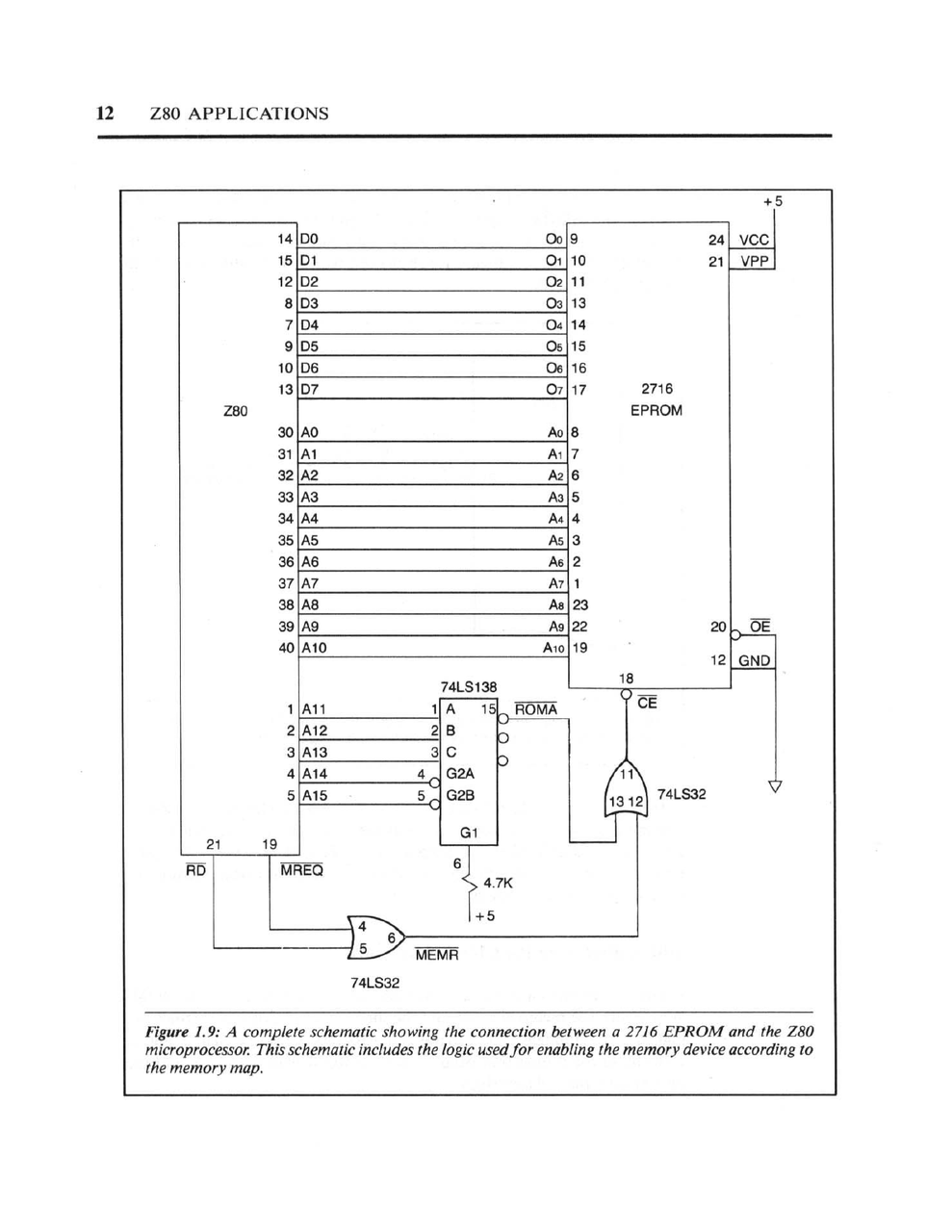
Figure 1.9 from the book: A complete schematic showing the connection between a 2716 EPROM and the Z80 microprocessor, including the logic used for enabling the memory device according to the memory map.
This single diagram requires understanding:
-
Address buses: The Z80 has 16 address lines (A0-A15). The 2716 EPROM has 11 address inputs. How do you connect them? Which lines go where?
-
Data buses: The Z80 has 8 data lines. The 2716 has 8 data outputs. These connect directly, but only when the chip is selected.
-
Chip select logic: The 74LS138 is a 3-to-8 decoder. The book explains how to use the upper address lines (A11-A15) to generate chip select signals, so that different memory chips respond to different address ranges. This is memory mapping, implemented in hardware.
-
Control signal generation: The Z80 outputs MREQ (memory request) and RD (read). These must be combined with OR gates to generate MEMR, which enables the ROM's output buffers at the correct moment.
The timing diagram that accompanies this schematic shows exactly when each signal transitions:
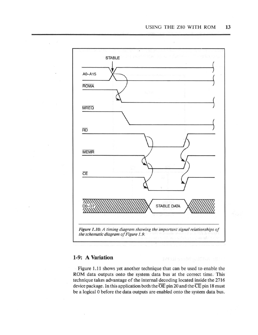
Figure 1.10: A timing diagram showing the important signal relationships. Address lines stabilize, MREQ goes low, RD goes low, data becomes valid, then everything releases.
This is page 12 of the book. We haven't written a single line of code yet. We're just trying to make the CPU able to read instructions from a ROM chip.
The Modern Equivalent: There Isn't One
On a Raspberry Pi, you don't connect the CPU to RAM. The RAM is soldered to the board. On an Arduino, the flash memory that holds your program is inside the microcontroller chip. There's no schematic to draw because there's no external connection to make.
When a modern tutorial says "upload your sketch," it's hiding:
- The USB-to-serial converter that talks to the bootloader
- The bootloader that receives bytes and writes them to flash
- The flash memory controller that handles page erasure and programming
- The reset circuit that starts execution at the right address
All of this exists. It's just not something you're expected to understand, or even know about, to get started.
Dynamic RAM: Where It Gets Serious
Chapter 4 of Coffron's book covers dynamic RAM. This is where the real complexity lives.
Static RAM is simple: you put an address on the bus, assert the chip select, and the data appears. Dynamic RAM is different. It stores bits in tiny capacitors that leak charge, so you have to refresh them periodically. It uses multiplexed addressing to reduce pin count. You send the row address, strobe RAS (Row Address Strobe), then send the column address and strobe CAS (Column Address Strobe).
The book dedicates an entire chapter to building a 16K x 8-bit dynamic RAM system using 4116 chips. This involves:
-
Address multiplexing hardware: You need logic to switch between presenting the low address bits and the high address bits to the RAM chips at the right times.
-
RAS/CAS timing generation: The sequence of RAS and CAS signals must meet strict timing requirements. Too fast and the chips don't respond. Too slow and you waste cycles.
-
Refresh logic: The Z80 has a built-in refresh counter (one of its innovations over the 8080), but you still need to understand when refresh cycles occur and how they interleave with normal memory access.
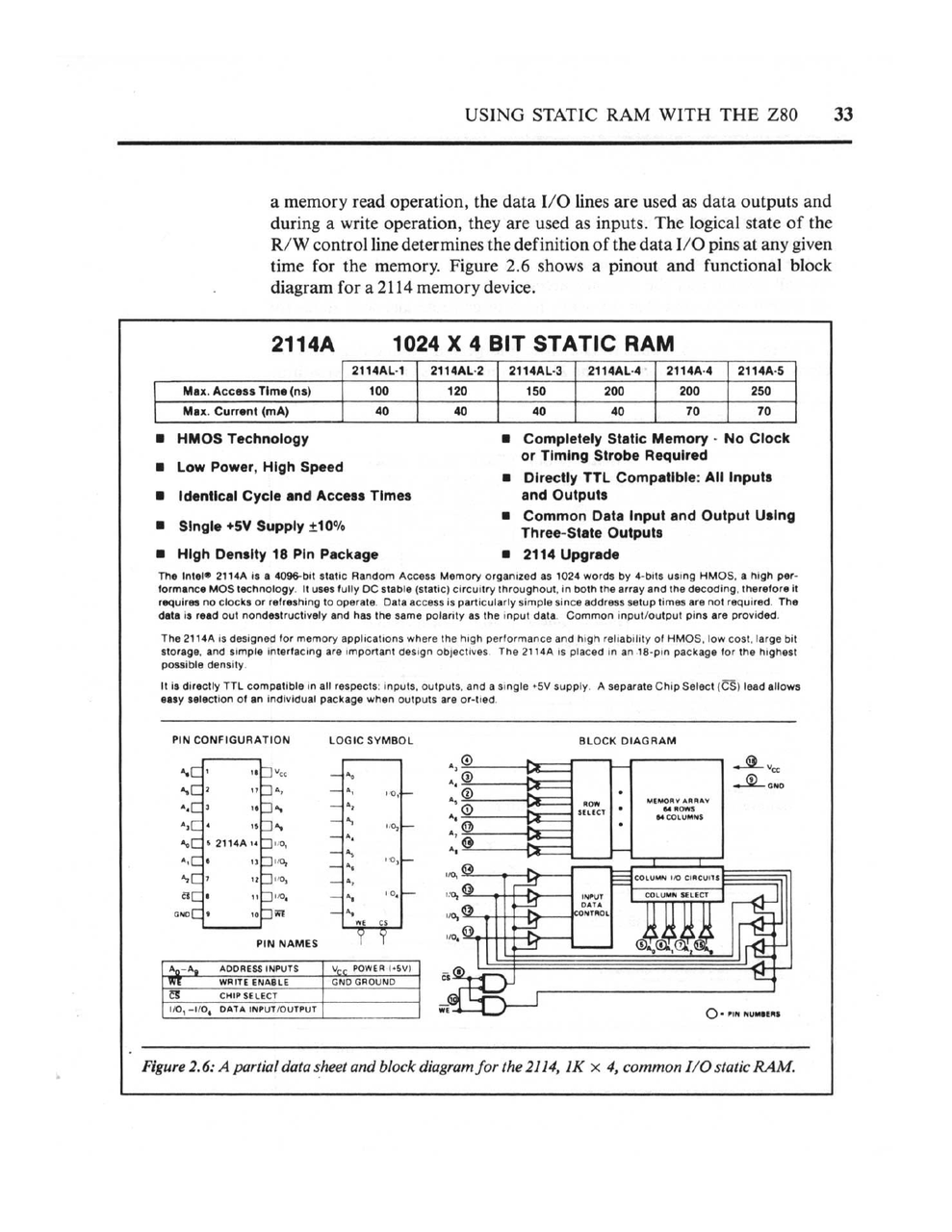
Figure 2.6: A partial data sheet and block diagram for the 2114, a 1K x 4 static RAM. The book walks through every pin and its function.
Here's the key insight: in 1983, if you wanted more than a few kilobytes of RAM, you had to use dynamic RAM. Static RAM was expensive. The 4116 gave you 16K bits for the same cost as 1K bits of static RAM. But you paid for it in complexity.
Today? The Raspberry Pi 5 has 8 gigabytes of DDR4 RAM. The timing controller, refresh logic, and address multiplexing are all handled by a dedicated memory controller inside the Broadcom SoC. You don't configure it. You don't even see it. It just works.
Interrupts: Where Software Meets Hardware
Chapter 5 covers interrupts, and this is where Coffron's book becomes genuinely fascinating. The Z80 has three interrupt modes, and the book explains not just what they do, but how to wire the hardware to use them.
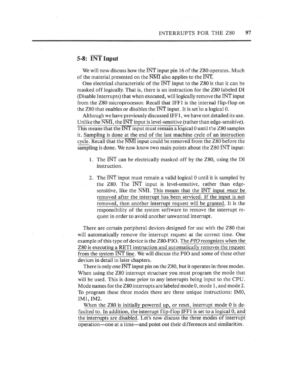
The book explains the electrical characteristics of the INT input, how to mask interrupts in software, and the three interrupt modes.
Mode 2 interrupts are particularly elegant. When an interrupt occurs:
- The interrupting device places a byte on the data bus
- The CPU reads this byte and combines it with the I register to form a 16-bit pointer
- This pointer addresses a table in memory containing the actual interrupt service routine address
- The CPU jumps to that address
This means you can have up to 128 different interrupt vectors, each pointing to a different handler, with the interrupting device choosing which one. The book shows how to set up the vector table in memory and how to wire multiple devices in a "daisy chain" priority scheme.
In Arduino-land, you write attachInterrupt(digitalPinToInterrupt(2), myFunction, RISING) and you're done. The hardware abstraction layer handles vector table management, priority, and dispatch. This is convenient. But you have no idea why pin 2 can trigger an interrupt and pin 4 can't (on an Uno), or what happens inside the CPU when an interrupt fires.
The Peripheral Chips: A Complete Ecosystem
The Z80 wasn't just a CPU; it was the center of a chip family. Zilog made matching peripheral chips designed to work together:
- Z80 PIO: Parallel I/O controller with handshaking
- Z80 CTC: Counter/Timer circuit for generating timing or counting events
- Z80 SIO: Serial I/O for RS-232 communication
- Z80 DMA: Direct Memory Access controller for fast block transfers
Coffron's book covers all of these, plus Intel's 8255 PIO and 8253 timer (which work with the Z80 despite being designed for the 8080).
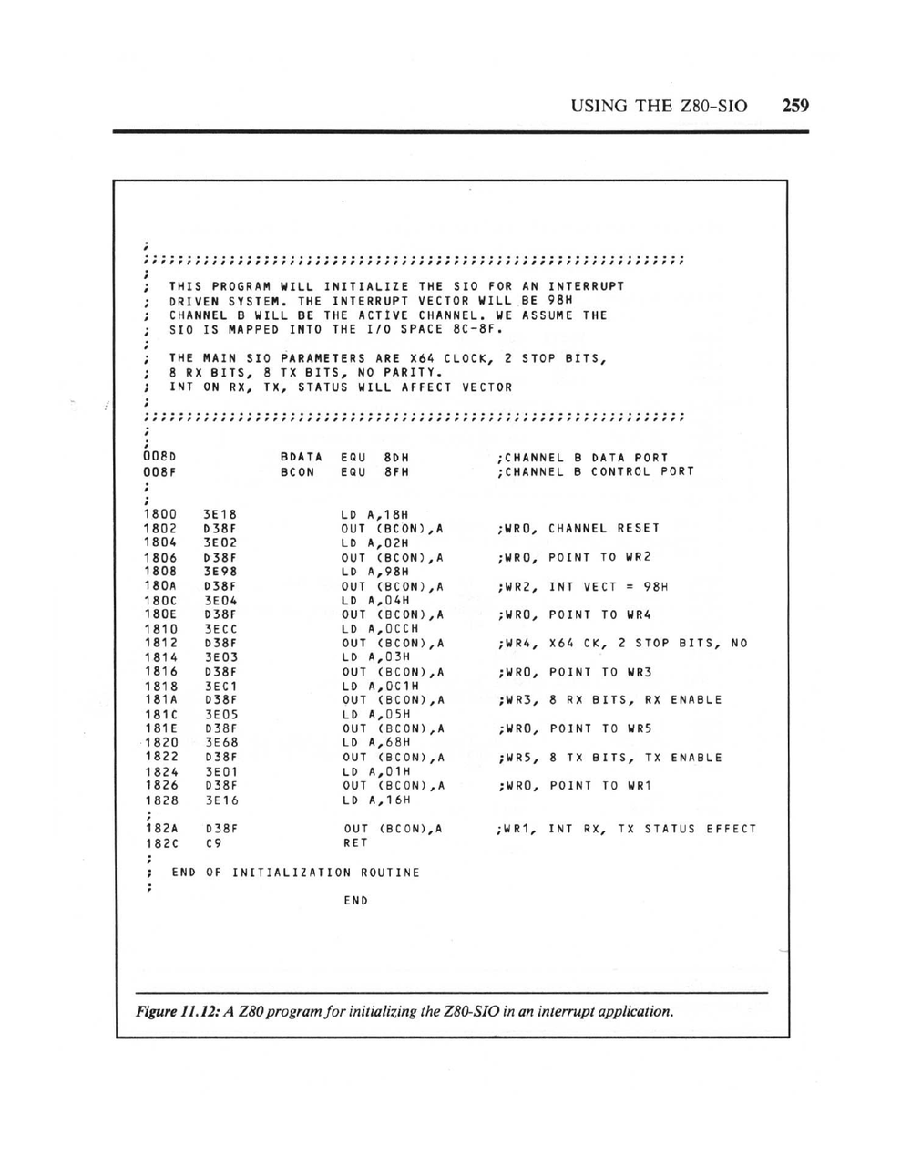
Figure 11.12: A Z80 program for initializing the Z80-SIO in an interrupt application. Every register must be programmed in the correct sequence.
Look at that initialization code. To set up a serial port, you have to:
- Write to the control port to select which internal register you want to access
- Write the actual configuration byte
- Repeat for each register (WR0 through WR7)
- Set up the interrupt vector
- Enable the receiver and transmitter separately
The SIO has eight write registers and three read registers per channel, each with specific bit-level meanings. The book includes an appendix that's just register descriptions, twelve pages of bit definitions.
Compare this to Arduino: Serial.begin(9600). One line. Done.
The Static Stimulus Tester: Debugging from First Principles
Chapter 12 is unlike anything you'll find in a modern tutorial. It describes building a "Static Stimulus Tester," a tool for debugging Z80 hardware by manually single-stepping the CPU.
The idea is simple but radical: disconnect the crystal oscillator and replace it with a push-button. Each press advances the CPU by one clock cycle. Add LED displays for the address bus, data bus, and control signals. Now you can literally watch the CPU execute, one clock tick at a time.
The book includes assembly language examples throughout, always tied to specific hardware configurations.
This is how engineers debugged hardware in 1983. No logic analyzer (those cost more than cars). No JTAG. No printf debugging. You built a tool that let you see electricity moving through your circuit, and you traced the problem by hand.
Modern development boards have LEDs. They blink to show activity. But they're diagnostic indicators, not debugging tools. If your Arduino doesn't work, you use the serial monitor to print messages. If that doesn't work, you post on Stack Overflow. The idea of building a hardware tool to watch your CPU execute instruction-by-instruction is genuinely alien to modern practice.
The Economics of Learning
It's worth considering what it actually cost to learn hardware in 1983.
The book itself was probably \$15-20. But to actually use it, you needed:
- A Z80 CPU: about \$10-15 in 1983 dollars
- 2716 EPROMs: \$5-10 each, and you'd need several
- 2114 static RAM chips: \$3-5 each, eight for a basic system
- 74LS-series logic chips: \$0.50-2 each, dozens needed
- Sockets, capacitors, resistors, wire: another \$20-30
- A prototype board or wirewrap supplies: \$10-50
- An EPROM programmer: \$100-300 for a basic unit
- An oscilloscope: \$300-1000 for something usable
- A power supply: \$30-50
A minimal setup to follow along with Coffron's book would run \$200-400 in 1983 dollars, roughly \$600-1200 in 2026 money. A serious hobbyist setup with a decent scope and programmer could easily hit \$1000-2000 (1983), or \$3000-6000 adjusted.
Compare that to an Arduino Uno: \$25. A Raspberry Pi: \$35-75. A USB cable you probably already own. Free software. Free tutorials. Free community support on forums and Discord.
The democratization isn't just about abstraction; it's about cost. In 1983, learning hardware was expensive enough that it filtered for a certain kind of person: someone with disposable income, access to electronics suppliers, and enough space for a workbench. Today, a teenager with a part-time job can afford to experiment.
This matters. The people who learned hardware in 1983 were a self-selected group. The people who learn today are everyone.
What We Gained and What We Lost
I want to be clear: I'm not arguing that the 1983 approach is better. The barriers to entry were enormous. Building a working Z80 system from Coffron's book required:
- Understanding digital logic (AND, OR, NAND gates)
- Reading timing diagrams
- Calculating address decoding logic
- Soldering dozens of chips onto a board
- Having access to an EPROM programmer
- Writing assembly language
This took months of study and significant equipment investment. The number of people who could do it was small.
Today, a complete beginner can have an LED blinking on an Arduino within an hour of opening the box. They can connect sensors, motors, and displays without understanding the underlying protocols. They can build genuinely useful things (home automation, art installations, scientific instruments) without ever reading a timing diagram.
This democratization is valuable. More people building more things is good.
But something is lost.
The modern approach creates a gap between "user" and "understander." You can use an Arduino without understanding it. You can use a Raspberry Pi as a Linux computer without knowing it has GPIO pins. You can run machine learning models without understanding matrix multiplication.
In 1983, there was no such gap. If you were using a microprocessor, you understood microprocessors. You had to. The abstraction layers didn't exist yet.
The Pedagogical Difference
Coffron's book teaches hardware by building it. Each chapter adds another subsystem: ROM, then RAM, then I/O ports, then interrupts, then timers, then serial communication. By the end, you understand how all the pieces connect because you connected them yourself.
Modern tutorials teach by doing. "Make this LED blink. Now make it blink faster. Now add a button. Now read a temperature sensor." The complexity is hidden, revealed only when you hit the limits of the abstraction.
Both approaches work. But they produce different kinds of understanding.
Someone who learned from Coffron's book can troubleshoot hardware. They can look at an oscilloscope trace and identify a timing problem. They can read a datasheet for a new chip and understand how to integrate it. They have a mental model of what the electricity is doing.
Someone who learned from Arduino tutorials can build things. They can iterate quickly, trying different sensors and actuators until something works. They can find libraries that solve their problems and examples they can modify. They have a mental model of what the software is doing.
Neither is wrong. But they're not the same thing.
What Would 1983 Make of 2026?
If you dropped a Raspberry Pi 5 on James Coffron's desk in 1983, what would he see?
A computer with four 64-bit CPU cores running at 2.4 GHz. Eight gigabytes of RAM. Gigabit Ethernet. Bluetooth. WiFi. USB. HDMI. A GPU capable of 4K video. Storage measured in terabytes.
And no way to understand any of it from first principles.
The SoC at the heart of a Raspberry Pi contains billions of transistors. The memory controller alone is more complex than every computer that existed in 1983 combined. The protocols (USB 3.0, HDMI 2.0, PCIe) are specified in documents thousands of pages long.
You can't build a Raspberry Pi from discrete components. You can't even build the chips that go into it without a billion-dollar fab. The abstraction isn't just convenient; it's necessary. The complexity has exceeded human ability to hold it in one head.
This is progress. But it's also a kind of loss.
Closing Thoughts
I keep Coffron's book on my shelf not because I'm going to build a Z80 system (though I might, someday), but because it represents a way of thinking about computers that's worth preserving.
The Z80 is comprehensible. One person can understand all of it: every instruction, every pin, every timing requirement. The peripheral chips are comprehensible too. A moderately determined person can read the datasheets and know exactly what the hardware is doing.
Modern computers are not comprehensible in this way. They're usable, powerful, and democratized. But they're also opaque, their complexity hidden behind layers of abstraction that most users will never penetrate.
Both things can be true. We can celebrate Arduino for making electronics accessible while acknowledging that something is different (not worse, but different) about a world where understanding and using have become separate activities.
If you want to experience what hardware education was like in 1983, find a copy of Coffron's book. It's out of print, but scanned PDFs exist. Read chapter 1. Draw the schematic on paper. Trace the signals with your finger. Try to understand not just what the circuit does, but why it works.
Then open the Arduino IDE and type digitalWrite(13, HIGH).
Both are valid. But they're not the same thing.
Resources
The Books
- Z80 Applications by James W. Coffron: The 1983 SYBEX book discussed in this article. Used copies occasionally appear.
- Build Your Own Z80 Computer by Steve Ciarcia: Another classic from 1981, showing how to construct a complete Z80 system from scratch.
- The Best of Ciarcia's Circuit Cellar: A collection of Steve Ciarcia's legendary BYTE magazine projects.
The Modern Approach
- Arduino Uno R3: The official board. Plug it in, upload a sketch, blink an LED.
- ELEGOO UNO R3 Most Complete Starter Kit: 200+ components with tutorials. Everything you need to get started.
- Raspberry Pi 5 (8GB): The computer that would have seemed like science fiction in 1983.
The 1983 Toolkit
- Hakko FX888D Soldering Station: A quality soldering station for building hardware the old-fashioned way.
- Rigol DS1054Z Oscilloscope: A 4-channel 50MHz scope. In 1983, this capability would have cost thousands.
- T48 Universal Programmer: Programs EPROMs, EEPROMs, and microcontrollers. Supports the vintage 27Cxxx series with high-voltage programming.