When I decided to run vintage Z80 code on a modern Arduino Giga R1, I hit an immediate roadblock: voltage incompatibility. The RetroShield Z80 by 8-Bit Force is a fantastic piece of hardware that lets you run a real Zilog Z80 processor on an Arduino, but it's designed for the 5V-tolerant Arduino Mega 2560. The Arduino Giga R1, with its powerful STM32H747 dual-core processor and 76 GPIO pins, operates at 3.3V logic levels and can be permanently damaged by 5V signals.
The solution? A custom shield with level shifters that could translate between the Giga's 3.3V world and the Z80's 5V domain. Rather than spend weeks learning PCB design software and risking amateur mistakes, I decided to outsource the work to a professional on Fiverr. Here's what that experience was like, including the full cost breakdown and everything I received.
The Project Requirements
My requirements were relatively straightforward on the surface:
- Design an Arduino Giga R1-compatible shield (matching the Giga's unique form factor)
- Include bidirectional level shifting from 3.3V to 5V on all relevant GPIO pins
- Provide pass-through headers so the RetroShield Z80 could plug in on top
- Use KiCad for the design (my preferred EDA tool for future modifications)
The Arduino Giga R1 is essentially a larger, more powerful cousin of the Arduino Mega 2560. It shares some pin compatibility but has a different physical layout with additional headers. The shield needed to accommodate all of this while providing level shifting for approximately 70+ digital I/O lines.
Why the Arduino Giga R1?
You might wonder why I chose the Arduino Giga R1 over other options. The Arduino Due, which I mentioned in my initial message to the designer, was my original consideration. It's also 3.3V logic and has a powerful ARM processor. However, the Giga R1 offers several compelling advantages:
Processing Power: The Giga R1's STM32H747 is a dual-core Cortex-M7/M4 running at 480MHz and 240MHz respectively. This dwarfs the Due's 84MHz Cortex-M3. For running Z80 code, this extra headroom means I could potentially implement cycle-accurate emulation or run multiple virtual Z80s simultaneously.
Memory: The Giga R1 has 2MB of internal flash and 1MB of RAM, plus it supports external memory. The Due has 512KB flash and 96KB RAM. More memory means I can load larger Z80 programs and implement more sophisticated peripherals.
Connectivity: The Giga R1 includes WiFi and Bluetooth out of the box. Imagine running a Z80 BBS that's actually accessible over the internet, or wireless file transfers to a CP/M system. The possibilities are intriguing.
Camera Support: The Giga R1 has a camera connector. While seemingly unrelated to Z80 computing, it opens doors for interesting projects like OCR input devices or barcode reading peripherals.
The trade-off is that the Giga R1's 3.3V logic requires level shifting for any 5V hardware, hence this project. The Mega 2560's 5V tolerance made the RetroShield plug-and-play, but I felt the Giga's advantages were worth the additional complexity.
Finding a Designer on Fiverr
Fiverr's PCB design category has hundreds of sellers ranging from hobbyists charging \$20 to professional engineers charging \$500+. After reviewing portfolios and reading reviews, I found a designer named Elijah (username: ekeziah) whose work looked professional and who specifically mentioned KiCad experience. He does PCB design, CAD, and firmware work.
His base gig was priced reasonably, but I knew custom work like this would require negotiation. I reached out with my requirements:
"I have a relatively straightforward project. I need an Arduino Due/Giga form factor shield that can use level shifters to go from 3.3V to 5V. I have this: [RetroShield link] which is 5V, and instead of using an Arduino Mega 2560, which is 5V tolerant, I want to use either an Arduino Due or Giga which is not tolerant of 5V."
The designer responded quickly and we began negotiating scope and pricing.
The Cost Reality Check
Let me be transparent about the costs because this is often glossed over in "I made a thing" posts:
Initial Order (January 4, 2026)
- Base price: \$75
- Custom extras negotiated: \$200
- Fiverr service fees: \$108.67
- Subtotal: \$383.67
The designer initially quoted \$175, then corrected himself saying it was a typo and meant \$275. We settled on a \$275 total for the custom work with a 7-10 day timeline. Fiverr's fees added roughly 28% on top.
Revision Order (January 20, 2026)
After receiving the initial files, I realized I wanted to add version numbering and my website URL to the silkscreen. Since the designer hadn't included the KiCad source files in the first delivery (only Gerber files), I needed him to make the changes and regenerate everything.
- Revision price negotiated: \$57
- Fiverr service fees: \$27.96
- Subtotal: \$84.96
Total Project Cost: \$468.63
Is this expensive? It depends on your perspective. A professional PCB design service might charge \$100-200 per hour, and this project involved creating a schematic from scratch, laying out a moderately complex board, and generating production files. Doing it myself would have taken 20-40 hours of learning and work. At that rate, the \$468 represents reasonable value, but it's definitely not pocket change for a hobby project.
The Design Process
Communication happened entirely through Fiverr's messaging system. Here's how the project unfolded:
January 4-8: Requirements Gathering
The designer studied the Arduino Giga R1 documentation and the RetroShield Z80 pinout. He asked clarifying questions about whether I needed level shifting on pins 22-53 (the additional digital pins on the Giga's side headers). I confirmed that yes, all pins needed level shifting to ensure full compatibility.
January 9: Schematic Complete
Elijah sent the first schematic PDF showing the circuit design. The approach was clean: nine TXB0108PW 8-bit bidirectional level shifter ICs, providing 72 channels of voltage translation. Each level shifter had proper decoupling capacitors and pull-up resistors on the output enable pins.
The TXB0108 is a popular choice for this application because it's bidirectional; you don't need to specify which direction each pin will operate, making it ideal for GPIO that might be configured as either input or output.
This is a key design decision worth understanding. Alternative level shifter approaches include:
- 74LVC245 bus transceivers: These require a direction control pin, which adds complexity when GPIO pins change direction dynamically
- Simple resistor dividers: Work for unidirectional high-to-low shifting, but not bidirectional
- MOSFETs with pull-ups: The classic BSS138 approach works well but requires one MOSFET per channel and can be slow
- Dedicated level shifter ICs: The TXB0108 auto-detects direction and handles both directions at high speed
The designer's choice of TXB0108 was sound; it simplifies the design and ensures the shield will work regardless of how the software configures each GPIO pin.
January 10: Layout and Routing
The physical layout came together quickly. The board dimensions are 155mm x 90mm, matching the Arduino Giga R1's footprint with additional space for the level shifter circuitry. The routing was done on a two-layer board, keeping things manufacturable at low-cost PCB fabs.
The designer sent progress images showing the component placement with the level shifter ICs arranged along the edges of the board, close to their respective pin headers.
January 10: First Delivery
The initial delivery included:
- Gerber files (ready for PCB manufacturing)
- BOM (Bill of Materials) in CSV and Excel formats
- 3D rendered images of the board
- Schematic PDF
- Component placement (CPL) file for assembly
What was missing from this first delivery: the KiCad source files. This became important later.
The Revision Request
After examining the delivered files, I noticed two things I wanted to change:
- Add "v0.1" to the board silkscreen for version tracking
- Add my website URL (https://tinycomputers.io/) for attribution
These are simple text changes, but without the KiCad source files, I couldn't make them myself. The Gerber files are essentially "compiled" output; you can view them and send them to a fab, but you can't easily edit them.
I reached out to the designer:
"Is it possible for you to add something to the silkscreen? I would like to add 'v0.1' to the 'ARDUINO GIGA R1 SHIELD', so that line would be 'ARDUINO GIGA R1 SHIELD v0.1'. And then in a smaller font, directly to the right of that above text, I would like 'https://tinycomputers.io/'. I would add these things myself but I am not seeing any KiCAD source files, the only things that open in KiCAD are the Gerber files."
We negotiated \$57 for the revision, which also included finally receiving the full KiCad source files. The revision took about two days, with a quick back-and-forth to remove quotation marks from around the URL that the designer had initially added.
What I Received: The Complete Deliverables
The final delivery package was comprehensive. Here's everything included:
Source Files (SRC_FILES/)
The complete KiCad project including:
-
AlexJ_bz_ArduinoGigaShield.kicad_pcb- PCB layout file -
AlexJ_bz_ArduinoGigaShield.kicad_sch- Schematic file -
AlexJ_bz_ArduinoGigaShield.kicad_pro- Project file - Multiple backup ZIPs showing the design evolution
Having the source files means I can make future modifications myself: adding features, fixing issues, or creating derivative designs.
Gerber Files (GERBER_FILES/)
Production-ready files for PCB manufacturing:
- Front and back copper layers (F_Cu.gbr, B_Cu.gbr)
- Solder mask layers (F_Mask.gbr, B_Mask.gbr)
- Silkscreen layers (F_Silkscreen.gbr, B_Silkscreen.gbr)
- Paste layers for SMD assembly (F_Paste.gbr, B_Paste.gbr)
- Board outline (Edge_Cuts.gbr)
- Drill files (PTH.drl, NPTH.drl)
- Gerber job file for fab house compatibility
These files can be uploaded directly to JLCPCB, PCBWay, OSH Park, or any other PCB fabrication service.
Bill of Materials (BOM/)
Component lists in both CSV and Excel formats:
| Reference | Qty | Value | Part Number |
|---|---|---|---|
| C1-C27 | 27 | 0.1uF | CC0603KRX7R9BB104 |
| R1-R9 | 9 | 10K | RC0603FR-0710KL |
| U1-U9 | 9 | TXB0108PW | TXB0108PWR |
| J1-J10 | Various | Pin Headers | DNP |
The "DNP" (Do Not Populate) entries for connectors indicate these would typically be hand-soldered rather than machine-placed, or sourced separately.
3D Renders (IMAGES/)
Professional-looking 3D renders showing:
- Top view with the Arduino Giga R1 mounted
- Bottom view showing the routing
- Angled perspective view
These are great for documentation and for visualizing how the final assembly will look.
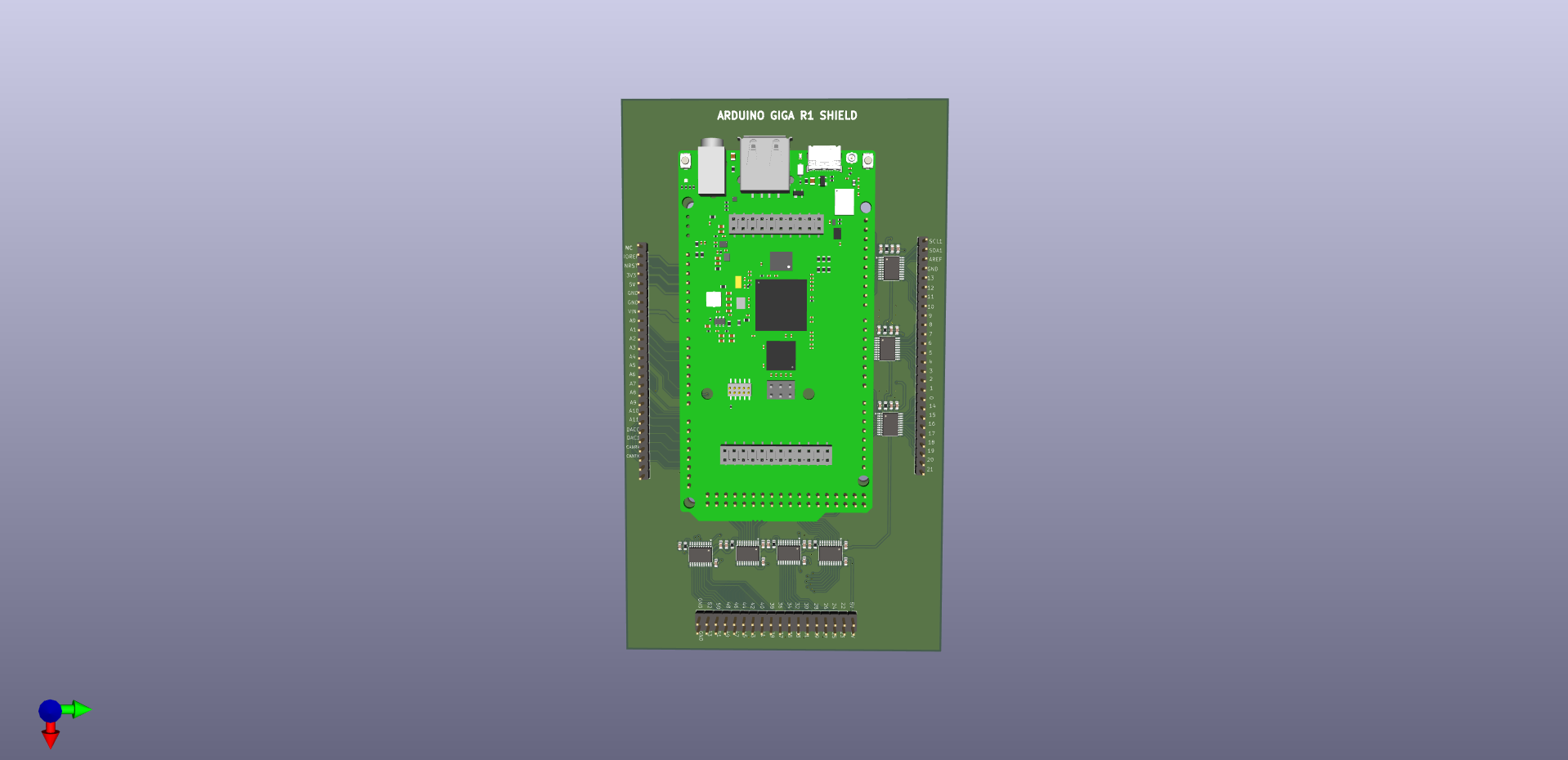
3D render showing the shield PCB with Arduino Giga R1 mounted (top view)
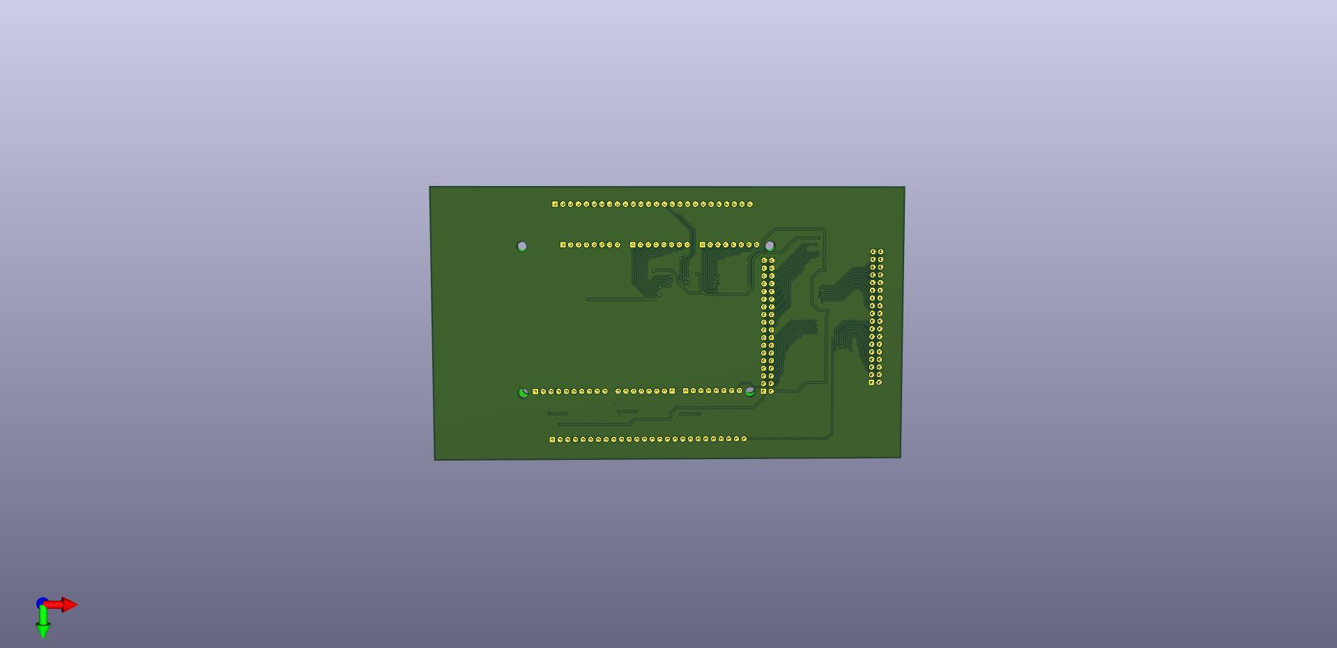
Bottom view showing the PCB routing and through-hole connections
Schematic PDF (SCH_PDF/)
A beautifully laid out schematic showing:
- All nine TXB0108PW level shifters with their connections
- Pin mapping from Arduino Giga headers to 5V output headers
- Power distribution (3.3V and 5V rails)
- Decoupling capacitor placement
- Four mounting holes for secure attachment
You can download the full schematic PDF here.
Reference Assets (ASSETS/)
The designer included reference materials used during the design:
- Arduino Giga R1 datasheet (2MB PDF)
- CAD files for the Arduino Giga R1 (ABX00063)
- STEP files for 3D modeling
- DXF file of the Giga R1 outline
These are helpful for understanding the design decisions and for future reference.
Component Placement File (CPL_FILE/)
A CSV file with X/Y coordinates and rotation for each component, useful if you're having the boards assembled by a fab house rather than hand-soldering.
The Circuit Design
Looking at the schematic, the design is elegant in its simplicity. Each TXB0108PW provides 8 channels of bidirectional level shifting. With nine of these ICs, the design provides 72 channels, more than enough for all the Arduino Giga's GPIO pins.
Key design elements:
Level Shifters: The TXB0108PW is an 8-bit bidirectional voltage-level translator. It automatically detects the signal direction, making it perfect for GPIO that might be configured as either input or output at runtime. The A-side connects to the 3.3V Arduino Giga pins, and the B-side connects to the 5V RetroShield pins.
Decoupling Capacitors: Each level shifter has a 0.1µF ceramic capacitor on both the 3.3V (VCCA) and 5V (VCCB) power pins. This is standard practice to filter high-frequency noise and ensure stable operation. With 27 capacitors total, the power rails should be rock-solid.
Output Enable Pull-ups: Each TXB0108 has a 10K pull-up resistor on the OE (Output Enable) pin, tying it to 3.3V. This ensures the level shifters are always active when the Arduino is powered.
Pass-Through Headers: The design includes matching pin headers on both the 3.3V and 5V sides. The Arduino Giga plugs into female headers on the bottom, while the RetroShield (or other 5V shields) can plug into male headers on top.
Lessons Learned
After going through this process, here's what I'd do differently or recommend to others:
1. Specify Source Files Upfront
Make it explicit in your initial requirements that you need the original design files (KiCad, Altium, Eagle, etc.), not just Gerber output files. This saves the cost and hassle of a revision later. Many designers consider source files an "extra" unless you ask for them.
2. Include Silkscreen Details Early
Think about what text you want on the board before the design starts. Version numbers, URLs, logos, regulatory markings: all of these are easy to add during initial design but require regenerating all files if added later.
3. Budget for Fiverr's Fees
Fiverr's service fees add roughly 25-30% to the listed price. When negotiating with a designer, account for this in your mental budget. A \$275 job becomes \$350+ after fees.
4. Communicate Frequently
Don't disappear for days at a time. Quick responses keep the project moving and help catch misunderstandings early. The designer asked good clarifying questions; make sure you answer them thoroughly.
5. Review Carefully Before Approving
Take time to review delivered files carefully. Open the Gerbers in a viewer (KiCad has a built-in Gerber viewer, or use an online tool), check the schematic for obvious errors, verify the BOM has the right components. It's much cheaper to catch issues before ordering PCBs.
Alternatives to Fiverr
Before deciding on Fiverr, I considered several alternatives:
DIY with KiCad: The open-source route. KiCad is free, powerful, and has excellent documentation. However, PCB design has a steep learning curve. Understanding design rules, proper trace widths, via sizes, clearances, and manufacturing constraints takes time. For a one-off project, the learning investment didn't seem justified.
Upwork or Other Freelance Platforms: Similar to Fiverr but often with higher prices and a more traditional freelancer relationship. Upwork tends to attract more experienced (and expensive) engineers. For a small project like this, Fiverr's fixed-price gig format seemed more appropriate.
Local EE Students/Engineers: Universities often have engineering students looking for small projects. This can be cheaper, but finding someone and managing the relationship takes effort. You also don't have the platform protections that Fiverr offers.
PCB Design Services: Companies like PCBWay and JLCPCB offer design services alongside manufacturing. These can be convenient but pricing varies widely and communication can be challenging across language barriers.
Open Source Existing Designs: Sometimes you can find an existing design that's close to what you need. I looked for Arduino Giga shields with level shifting but found nothing. The Giga R1 is relatively new and its unique form factor means fewer compatible shields exist.
Fiverr won because of its accessibility, fixed pricing model, and the portfolio/review system that let me evaluate designers before committing.
Was It Worth It?
For my situation, absolutely. I have a professional-quality PCB design that I can manufacture, modify, and iterate on. The alternative was spending 20-40 hours learning PCB design from scratch and likely making beginner mistakes that could damage expensive hardware.
The \$468 total is significant for a hobby project, but context matters:
- The Arduino Giga R1 costs \$90
- The RetroShield Z80 costs \$65
- PCB manufacturing will add another \$20-50 depending on quantity
The total investment for this Z80-on-Giga project will be around \$650-700 including the shield design. That's real money, but for a unique piece of hardware that lets me run authentic Z80 code on a modern microcontroller with WiFi, Bluetooth, and a camera interface, it feels worthwhile.
A Note on Maker Culture
I'm aware that hiring someone to design a circuit board runs counter to the ethos of Maker Culture. There's something deeply satisfying about designing, building, and debugging your own hardware, learning from mistakes, understanding every trace and component choice, and earning that sense of accomplishment that comes from true DIY.
Outsourcing the design felt like a shortcut, and in some ways it was. I traded the learning experience for speed and convenience.
That said, I didn't stop there. After receiving the Fiverr design, I also created an alternative version of the shield myself. I used Claude Code to help work through the component connections and pin mappings, and Quilter.ai to handle the PCB routing, an AI-powered tool that automates trace layout while respecting design rules. The result is a second design that I understand more intimately, having been involved in every decision.
Once PCBWay manufactures both versions, I'll post a comparison of the two approaches: the professionally designed Fiverr board versus the AI-assisted DIY version. It should be an interesting look at how modern AI tools are changing what's possible for makers who want to learn by doing but also want a safety net of intelligent assistance.
Next Steps
With the design files in hand, my next steps are:
- Order prototype PCBs from JLCPCB or PCBWay
- Source components from LCSC or DigiKey (the BOM helps here)
- Assemble and test the prototype
- Document any issues and potentially order a v0.2 revision
- Write about running Z80 code on the Arduino Giga R1
The beauty of having the KiCad source files is that if I find issues during testing, I can fix them myself and generate new Gerber files. The \$57 revision cost to get those source files has already paid for itself in peace of mind.
Conclusion
Fiverr can be a viable option for custom PCB design, especially for projects that are well-defined and don't require extensive back-and-forth iteration. The key is finding a competent designer, communicating clearly, and budgeting realistically for both the designer's fee and Fiverr's platform fees.
My Arduino Giga R1 shield project cost \$468.63 total across two orders, more than I initially hoped to spend, but less than I would have paid for my own time learning PCB design. The deliverables were comprehensive, professional, and gave me everything I need to manufacture, modify, and document the design.
If you're considering using Fiverr for PCB design, go in with realistic expectations about cost and timeline, and make sure to specify exactly what deliverables you need upfront. It might not be the cheapest option, but for a one-off custom project, it can be a reasonable trade-off between time and money.
Now, if you'll excuse me, I have some prototype PCBs to order and a Z80 to make talk to an STM32.
Coming Soon: Thanks to an upcoming sponsorship from PCBWay, I'll be able to bring this design from KiCad files and Gerber renders into the physical world. Stay tuned for a follow-up post where I'll document the manufacturing process, assembly, and first power-on of the Arduino Giga R1 Level Shifter Shield. Will it work on the first try? Will the Z80 finally talk to the STM32? Check back to find out!
The files discussed in this post, including the schematic and 3D renders, are from the actual delivered project. The Arduino Giga R1 is a product of Arduino. The RetroShield Z80 is designed by 8-Bit Force and available on Tindie.